
Description
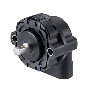
Williams Controls WM-H10 Non-Contact Rotary Position Sensor
The Williams Controls WM-H10 Non-Contact Rotary Position Sensor is a robust, shaft-operated Hall-effect position sensor designed for accurate and reliable measurement of angular position in demanding industrial, commercial vehicle and mobile equipment applications. Combining non-contact sensing technology, dual electrically isolated outputs and a compact mechanical design, the WM-H10 provides a dependable solution for applications where accurate rotational position feedback and long operating life are essential.
Designed as a solid-state rotary position sensing solution, the WM-H10 converts the angular position of its 6 mm D-profile shaft into proportional electrical output signals. The sensor can be configured with a measurement range from 15° through to 360° in 1° increments, providing equipment manufacturers and system designers with considerable flexibility when matching the sensor to the required mechanical movement.
A key feature of the WM-H10 is its dual-channel architecture. Two independent Hall-effect measuring circuits provide electrically isolated outputs, with each circuit having its own +5 VDC supply connection. This arrangement allows the two signals to be compared by the receiving electronic control system, providing an effective method of checking signal validity and supporting applications where diagnostic capability and dependable position feedback are important.
The non-contact Hall-effect sensing principle also eliminates the conventional resistive track and wiper arrangement found in traditional potentiometric position sensors. By reducing dependence on contacting sensing elements, the WM-H10 is capable of providing excellent durability in high-cycle applications and is specified for a mechanical life of up to 10 million cycles at 1 Hz.
Engineered for challenging operating environments, the WM-H10 provides resistance to temperature extremes, humidity, vibration, shock, dust and water exposure. This makes the sensor particularly suitable for hostile on-highway and off-highway vehicle environments as well as industrial equipment requiring dependable angular position measurement.
For Australian OEMs, engineers, vehicle manufacturers, system integrators and equipment operators, Control Devices Pty Ltd can assist with the selection and supply of Williams Controls WM-H10 Non-Contact Rotary Position Sensors for new equipment, specialised applications and compatible replacement requirements.
Advanced Non-Contact Hall-Effect Position Sensing
At the heart of the Williams Controls WM-H10 is non-contact Hall-effect sensing technology. Hall-effect sensors measure changes in a magnetic field and use this information to determine the position of a rotating component. In the WM-H10, this principle enables angular shaft position to be converted into a corresponding electrical output without relying on a conventional mechanically contacting resistive sensing element.
This approach provides significant advantages in applications involving frequent or continuous movement. Traditional potentiometric position sensors typically use a mechanical wiper moving across a resistive track. Although this technology remains suitable for many applications, repeated movement can eventually cause wear to the contacting components.
The WM-H10’s non-contact sensing principle removes this type of wear from the primary position measurement process. As a result, the sensor is particularly well suited to high-cycle applications where long service life, repeatable output and consistent performance are important.
The internal magnet arrangement is designed to maintain consistent separation between the sensing element and magnet. Maintaining this relationship helps minimise measurement errors that could otherwise result from variations in the air gap between the magnetic and sensing components.
The result is a compact rotary position sensor capable of providing reliable absolute angular position information across a configurable measurement range while maintaining the durability required for demanding vehicle and industrial environments.
Configurable Measurement Range from 15° to 360°
One of the most useful characteristics of the WM-H10 is its flexible angular measurement range. The full-range electrical output can be configured to correspond to rotational movement between 15° and 360°, with measurement ranges selectable in 1° increments.
This flexibility enables the sensor to be adapted to a broad variety of mechanical systems. Some applications may require accurate measurement across a relatively small angular movement, while others may require monitoring across a substantially larger rotation. The WM-H10 platform can accommodate both requirements without requiring completely different sensor technologies.
For example, a control lever, valve mechanism or linkage may only move through a limited angular range. Configuring the electrical output to correspond closely with that mechanical movement allows the available output span to be utilised effectively across the required operating range.
Alternatively, applications requiring considerably greater angular movement can utilise measurement ranges extending through to a complete 360° rotation.
The sensor itself provides 360° continuous mechanical rotation, while the programmed electrical measurement range determines the angular span over which the required proportional output is generated.
This combination of mechanical rotation capability and configurable electrical measurement range provides OEM engineers and system designers with significant flexibility when incorporating the WM-H10 into new equipment or specialised control systems.
Dual Independent and Electrically Isolated Outputs
The WM-H10 has been designed with two independent measuring circuits. Rather than simply providing a single position signal, the sensor incorporates dual Hall-effect sensing channels capable of supplying independent position information to the receiving electronic system.
Each measuring circuit has its own +5 VDC power supply connection and the channels are electrically isolated from one another. This architecture enables the receiving controller to monitor and compare the two output signals.
In an appropriate control system, one output can be utilised as the primary source of rotational position information while the second can be used for diagnostic comparison. The controller can evaluate the relationship between the two channels and determine whether the position information remains consistent with the expected correlation.
This provides system designers with an additional method of monitoring signal integrity. Rather than relying exclusively on a single position channel, the electronic control architecture can utilise information from both outputs when determining the validity of the sensor signal.
The WM-H10 is specified with output correlation of ±2%, providing defined performance between the two measurement channels.
This dual-channel architecture makes the WM-H10 particularly valuable for sophisticated electronic control systems where diagnostic capability and signal monitoring are important design considerations.
Fail-Safe Output Characteristics
In addition to its independent measurement circuits, the WM-H10 incorporates fail-safe output behaviour intended to assist the receiving control system in recognising electrical connection faults.
The sensor outputs are designed to enter predefined states when certain connection errors occur. This provides the host electronics with information that can assist in distinguishing normal position signals from abnormal electrical conditions.
For applications involving electronic vehicle controls or other important machine functions, the ability to identify abnormal sensor conditions can form a valuable part of the overall system diagnostic strategy.
The sensor itself is therefore more than a simple angular measurement device. Its dual independent circuits, signal correlation capability and predefined fault behaviour allow it to be incorporated into electronic architectures designed to continuously evaluate the validity of position information.
The exact diagnostic strategy remains dependent on the receiving controller and overall machine design, but the WM-H10 provides sensor-level characteristics that support sophisticated monitoring techniques.
Proportional Voltage Output for Accurate Position Measurement
The WM-H10 provides a linear voltage output proportional to the absolute angular position of the sensor shaft. This allows the receiving electronic controller to determine mechanical position by monitoring the corresponding electrical signal.
The specified output voltage is 10% to 90% of the supply voltage across the programmed measurement range, with a tolerance of ±2%. With the nominal 5 V supply used by the sensor, the output therefore operates within a defined portion of the available supply range.
The monotonic range is specified from a nominal 5%, or 0.25 V, through to 95%, or 4.75 V. The sensor has a specified linearity of ±2%, supporting dependable position measurement across the configured angular range.
By providing an analogue voltage proportional to absolute shaft position, the WM-H10 can be integrated into compatible electronic controllers, vehicle ECUs and industrial control systems capable of interpreting the sensor output.
The actual output law and measurement span should be selected according to the mechanical movement and electrical requirements of the intended application.
Independent 5 VDC Supply Architecture
The WM-H10 operates from a nominal 5 VDC supply, with the specified supply voltage being 5 VDC ±0.5 VDC. Each of the two measurement channels has an independent supply connection, reinforcing the electrical separation between the sensor circuits.
Supply current is specified at 10 mA per channel, allowing the WM-H10 to provide its dual-channel functionality with relatively low electrical demand.
The independent supply architecture is particularly valuable when the sensor is integrated into control systems designed to monitor multiple independent position channels.
Rather than sharing a single internal measurement circuit, the two Hall-effect channels can operate independently and provide separate outputs to the receiving electronics.
This enables the host controller to implement signal comparison algorithms appropriate to the equipment’s control strategy and diagnostic requirements.
Electrical Protection for Demanding Applications
Electronic sensors used in vehicles and industrial machinery can be exposed to electrical conditions that differ substantially from those encountered in controlled laboratory environments. Incorrect wiring, supply transients and short-circuit conditions must therefore be considered when designing robust electronic components.
The WM-H10 incorporates several electrical protection characteristics intended to improve resilience in demanding installations.
The sensor provides indefinite short-circuit protection for output-to-ground and output-to-supply conditions. It also provides reverse polarity protection up to -12 VDC and over-voltage protection up to 24 VDC.
These characteristics provide an additional level of protection for the internal electronics and complement the sensor’s fail-safe output design.
Correct wiring and installation according to the applicable technical documentation remain essential. However, the inclusion of electrical protection features demonstrates that the WM-H10 has been developed specifically for demanding vehicle and industrial environments where robust electronic design is important.
Compact 6 mm D-Profile Shaft Design
Mechanical connection to the WM-H10 is provided through a 6 mm D-profile shaft. The D-shaped profile provides a defined mechanical interface between the sensor shaft and the component whose angular position is being measured.
This shaft-operated configuration makes the WM-H10 suitable for applications where direct rotational engagement with a lever, linkage, valve, control mechanism or other rotating assembly is required.
The sensor provides 360° continuous mechanical rotation, allowing considerable flexibility when designing the mechanical interface.
With a total weight of less than 70 grams, the WM-H10 also provides substantial sensing capability within a compact and lightweight package. This can be particularly useful where installation space or component weight must be considered during equipment design.
By integrating the Hall-effect sensing system, magnetic arrangement, shaft mechanism and electrical connector into a compact assembly, the WM-H10 provides equipment designers with a practical solution for incorporating absolute rotary position feedback into a wide variety of systems.
Engineered for High-Cycle Operation
Rotary position sensors used in commercial vehicles and industrial machinery may be required to perform millions of movements throughout the operational life of the equipment. Sensor durability is therefore an important consideration when selecting a position feedback device for high-utilisation applications.
The Williams Controls WM-H10 is specified for a life of 10 million cycles when operated at 1 Hz. This high-cycle capability reflects both its robust mechanical construction and its use of non-contact Hall-effect position sensing technology.
Because the primary position measurement does not depend upon a conventional contacting resistive track, repeated shaft movement does not produce the same sensing-element wear mechanism associated with traditional potentiometric technology.
This makes the WM-H10 particularly attractive for applications where the monitored mechanism moves regularly throughout the operating day.
For OEMs and equipment operators, extended sensor life can contribute to improved system reliability and may help reduce the frequency of sensor replacement over the service life of the machine.
Designed for Harsh On-Highway and Off-Highway Environments
The WM-H10 has been engineered for environments where position sensors may be exposed to substantially more demanding conditions than conventional indoor electronic equipment.
On-highway commercial vehicles and off-highway machinery can expose sensors to continuous vibration, mechanical shock, water, dust, humidity, temperature extremes and electrical interference. The WM-H10 has therefore been designed with environmental robustness as a central characteristic.
The specified operating temperature range extends from -40°C to +85°C in accordance with SAE J1455 environmental considerations, while the storage temperature range extends from -40°C to +105°C.
The sensor has also been specified for random broadband vibration from 5 Hz to 500 Hz at 4.0 g and shock testing involving a one-metre drop onto concrete in accordance with the applicable SAE J1455 test requirement.
These characteristics make the WM-H10 well suited to applications where reliable angular position information must be maintained despite demanding mechanical and environmental conditions.
Exceptional Environmental Protection for Demanding Installations
The Williams Controls WM-H10 Non-Contact Rotary Position Sensor has been developed for applications where reliable position measurement must continue despite exposure to challenging environmental conditions. Commercial vehicles, off-highway equipment and industrial machinery can subject sensors to water, dust, mud, vibration, humidity and significant temperature changes throughout their operating life.
To address these demanding conditions, the WM-H10 incorporates a rugged housing and environmentally protected electronics. When configured with the appropriate GT Series connector, the electronic assembly provides protection to IP68 and IP69K levels, making the sensor particularly well suited to installations where exposure to water and contamination is an important consideration.
IP68 protection provides a high level of resistance against dust ingress and water exposure under the applicable test conditions. IP69K protection further addresses demanding high-pressure and high-temperature water exposure, which can be particularly relevant to equipment subjected to intensive cleaning procedures.
This level of environmental protection makes the WM-H10 suitable for applications where a conventional lightly protected position sensor may not provide sufficient resistance to the surrounding operating environment.
Actual environmental performance depends on the complete installation, connector selection, wiring arrangement and mating components. Correct installation procedures should therefore always be followed to maintain the intended protection of the sensor system.
Reliable Operation Across Extreme Temperatures
Industrial machinery and mobile equipment can operate across substantially different temperature conditions. Equipment may remain outdoors overnight in extremely cold environments before operating for extended periods under elevated temperatures generated by the surrounding climate, engine compartment or machine systems.
The WM-H10 has a specified operating temperature range from -40°C to +85°C. This broad range enables the sensor to support equipment intended for operation across diverse climatic and environmental conditions.
The specified storage temperature capability extends even further, from -40°C through to +105°C. This provides additional environmental tolerance when equipment or spare components are stored under conditions outside the normal operating temperature range.
Temperature capability is particularly important for precision electronic sensors because significant thermal changes can influence materials, electronic components and mechanical assemblies. The WM-H10 has therefore been engineered as a vehicle-grade position sensing solution rather than a sensor intended exclusively for controlled indoor environments.
Resistance to Vibration in Mobile Equipment
Vibration is a constant consideration when selecting electronic components for commercial vehicles and mobile machinery. Engine operation, drivetrain movement, road surfaces, hydraulic equipment and normal machine operation can transmit continuous vibration through the equipment structure and into mounted sensors.
The WM-H10 is designed to withstand demanding vibration conditions associated with these applications. Its published environmental performance includes random broadband vibration testing over a frequency range from 5 Hz to 500 Hz at 4.0 g.
This resistance is particularly valuable for applications where the sensor is mounted directly to a control mechanism or machine assembly exposed to continuous movement.
A rotary position sensor must not only survive these conditions mechanically but must also continue providing dependable position information to the electronic controller. The robust construction of the WM-H10 therefore complements its non-contact Hall-effect sensing technology to provide a position measurement solution suited to mobile equipment environments.
Mechanical Shock Resistance
In addition to continuous vibration, components used on industrial and mobile equipment may experience mechanical shock during manufacture, installation, transportation, maintenance or operation.
The WM-H10 has been designed with resistance to demanding mechanical conditions in mind. Its environmental specifications include shock performance based on a one-metre drop onto concrete under the applicable SAE J1455 test conditions.
This ruggedness reinforces the suitability of the sensor for professional equipment applications where components cannot always be protected from every mechanical impact encountered during their service life.
While appropriate installation and handling remain essential, the sensor’s robust mechanical design provides an additional level of confidence for engineers selecting a rotary position sensor for demanding environments.
Humidity and Moisture Resistance
High humidity can present significant challenges for electronic components, particularly when equipment moves between different temperature environments where condensation may occur.
The WM-H10 is designed to operate reliably in high-humidity conditions, complementing the environmental sealing of its electronic assembly.
This capability is especially important for equipment operating outdoors, in coastal regions, around wash-down areas or in applications where temperature changes can result in moisture forming around electronic components.
Combined with the sensor’s IP68/IP69K environmental protection when appropriately configured, resistance to humidity helps make the WM-H10 suitable for applications requiring dependable position feedback in challenging outdoor and mobile environments.
Suitable for Exposed and Wash-Down Environments
Many commercial and off-highway machines require regular cleaning to remove dirt, mud, dust and other contaminants. Components installed on these machines can consequently be exposed to water spray and demanding cleaning environments.
The environmental protection available with the WM-H10 makes it particularly attractive for applications where this type of exposure must be considered during sensor selection.
When installed using the appropriate GT Series connector configuration, the IP69K-rated electronic assembly provides a high degree of protection against high-pressure water exposure under the defined test conditions.
This does not eliminate the need for good system design. Connector interfaces, cable routing, mechanical mounting and surrounding components should all be selected and installed in a way that maintains the intended environmental integrity of the complete sensing system.
For OEM designers, considering environmental protection at the component-selection stage can help avoid introducing vulnerable electronic devices into exposed areas of a vehicle or machine.
Electromagnetic Compatibility for Electronic Control Systems
Modern vehicles and industrial machines contain a growing number of electronic devices. Engine controllers, electric motors, alternators, solenoid valves, communication networks, power electronics and radio equipment can all contribute to the electromagnetic environment surrounding a position sensor.
A rotary position sensor installed in these systems must be designed to provide dependable signals despite the electrical conditions associated with the application. The WM-H10 has been developed with electromagnetic compatibility requirements relevant to vehicle environments in mind.
This characteristic complements the sensor’s electrical protection features, including reverse polarity, over-voltage and output short-circuit protection.
For system designers, appropriate cable routing, grounding, connector selection and controller input design remain important aspects of achieving reliable electromagnetic compatibility throughout the complete installation.
Rugged Connector Options
Reliable position sensing depends not only on the sensor itself but also on the electrical connection between the sensor and the receiving control system. Connector integrity is particularly important in applications exposed to vibration, moisture, dust and temperature changes.
The WM-H10 is available with connector arrangements intended for demanding vehicle and industrial applications. The GT Series connector option is particularly significant because it enables the electronics to achieve the specified IP68 and IP69K environmental protection when correctly installed.
The dual-channel architecture requires connections for the independent supply and signal circuits. Correct wiring is therefore essential to ensure that both measurement channels operate according to the intended system design.
When specifying the WM-H10, engineers should confirm the required connector arrangement, pin configuration, mating connector and harness requirements as part of the overall sensor selection process.
Control Devices can assist customers with identifying an appropriate WM-H10 configuration based on the intended electrical interface and application requirements.
Accurate Absolute Angular Position Feedback
The WM-H10 provides absolute angular position feedback. This means the electrical output represents the physical angular position of the shaft within the configured measurement range.
For the receiving electronic controller, this provides direct information about the position of the mechanical component connected to the sensor.
Depending on the application, this position information may represent the movement of a control lever, valve, actuator, linkage, pedal mechanism, steering-related assembly or another rotating component.
The configurable electrical measurement range allows the sensor output to be matched closely to the mechanical movement being monitored. With available ranges from 15° to 360° in 1° increments, engineers can select an angular span appropriate to the application.
This is particularly valuable where the mechanical mechanism uses only a limited portion of a complete rotation. Rather than using a fixed 360° electrical range for every application, the WM-H10 can be configured so the useful electrical output corresponds more closely with the actual movement of the mechanism.
Flexible Rotation and Output Configuration
Different machines can require very different relationships between mechanical rotation and electrical output. The WM-H10 platform provides configuration flexibility to accommodate these varying requirements.
The sensor offers continuous 360° mechanical rotation, while the active electrical measurement range can be configured according to the intended application. This provides engineers with considerable freedom when determining the sensor’s mounting orientation and relationship with the monitored mechanism.
The direction and output characteristics must be correctly specified for the intended control system. The receiving controller should be configured to interpret the sensor output according to the programmed relationship between shaft position and output voltage.
Careful specification at the design stage can provide an efficient use of the available electrical output range and support accurate measurement of the mechanism throughout its required travel.
Dual-Channel Monitoring for Enhanced Diagnostics
The two electrically isolated measurement channels incorporated into the WM-H10 provide an important advantage for applications requiring advanced signal diagnostics.
Each channel has an independent 5 VDC supply and produces its own output signal. A compatible electronic controller can therefore monitor both signals and compare their relationship during operation.
Under normal operating conditions, the outputs should maintain the expected correlation. If the relationship moves outside the acceptable limits defined by the overall control system, the controller can potentially identify an abnormal condition and respond according to the machine’s programmed diagnostic strategy.
The WM-H10 specifies output correlation of ±2%, providing a defined relationship between the measurement channels.
This architecture can be particularly valuable in electronic vehicle and machine control systems where dependable position information is required and where the controller is designed to perform plausibility checking between multiple sensor signals.
The dual-channel sensor itself should be considered as one component within the overall control and diagnostic architecture. Functional safety and machine safety requirements must be assessed at the complete system level by the equipment designer.
Ideal for Lever and Operator Control Position Sensing
One potential application for the WM-H10 is the measurement of lever position in electronic operator controls. A mechanical lever can be connected directly or through an appropriate linkage to the sensor’s D-profile shaft, allowing angular movement to be translated into an electronic position signal.
This approach can be used in control systems where an operator’s mechanical input must be communicated electronically to a machine controller.
The configurable measurement range is especially useful in these applications because control levers often move through significantly less than a complete 360° rotation. The WM-H10 can be configured with an electrical range appropriate to the actual lever travel.
Its high-cycle Hall-effect sensing technology is also advantageous for operator controls that may be moved thousands of times during normal machine operation.
Valve and Actuator Position Feedback
Rotary position sensing can also be required where an electronic controller needs feedback regarding the position of a valve, actuator or other rotating mechanism.
By mechanically coupling the WM-H10 to the relevant shaft or linkage, the sensor can provide an electrical representation of angular position to the control system.
This information can then be used by the machine controller according to the requirements of the application. Potential functions may include position monitoring, closed-loop control, diagnostic comparison or operator display information.
The sensor’s compact size and 6 mm D-profile shaft provide a practical mechanical interface for integration into many specialised assemblies.
For applications involving substantial shaft loads or mechanical forces, the surrounding linkage should be designed so the sensor is used primarily as a position measurement device rather than as a structural component of the mechanism.
Throttle and Engine Control Applications
Williams Controls has extensive experience in electronic throttle and vehicle control technology, and the WM-H10 can be considered for applications where rotational movement must be converted into a dependable electrical position signal within a compatible engine or vehicle control system.
Depending on the machine architecture, rotary position sensing may be used to monitor throttle-related mechanisms, control linkages or other rotational inputs associated with engine and propulsion control.
The WM-H10’s dual-channel output architecture can be especially useful in applications where the receiving controller is designed to compare independent position signals.
However, sensor configuration and compatibility must always be verified against the requirements of the specific engine controller or electronic control unit. Supply voltage, output range, direction of operation, angular measurement range, connector configuration and diagnostic strategy should all be confirmed before integration.
Suitable for On-Highway Commercial Vehicles
The WM-H10’s environmental resistance and robust electronics make it suitable for consideration in commercial vehicle applications requiring accurate angular position feedback.
Heavy trucks, buses, coaches and specialised road vehicles contain numerous mechanical systems whose positions may need to be monitored electronically. Depending on the vehicle architecture, these can include operator controls, actuators, linkages and other rotating mechanisms.
Commercial vehicles can also accumulate substantial operating hours and may travel through dramatically different environmental conditions. The WM-H10’s high-cycle non-contact sensing technology and broad operating temperature range provide important advantages in these demanding applications.
Designed for Off-Highway Machinery
Off-highway equipment presents some of the most challenging conditions encountered by electronic sensors. Construction machinery, agricultural equipment, material handling vehicles and specialised mobile machines can expose components to continuous vibration, dust, mud, water and repeated cleaning.
The WM-H10 is well suited to these types of environments due to its rugged construction and high environmental protection.
Its non-contact sensing technology also provides an important advantage in machinery where a rotary position sensor may be operated repeatedly throughout long working shifts.
Applications can include control levers, actuator position monitoring, linkage feedback and other rotational measurement tasks where the equipment controller requires accurate position information.
Industrial Machinery and OEM Integration
Although the WM-H10 is particularly well suited to vehicle environments, its characteristics can also make it an effective solution for specialised industrial machinery.
OEM equipment manufacturers may require compact position sensors capable of surviving harsher operating conditions than conventional industrial potentiometers. In these applications, the WM-H10 provides the advantages of non-contact Hall-effect sensing together with environmental protection and a configurable angular measurement range.
The dual independent outputs can also provide additional diagnostic capability where the machine control architecture is designed to monitor multiple position signals.
For new OEM designs, engineers can select the measurement range and electrical configuration according to the mechanical travel and controller requirements of the equipment.
Important Considerations When Selecting a WM-H10
Selecting the correct WM-H10 configuration requires consideration of both the mechanical and electrical requirements of the application. Although sensors within the WM-H10 family share the same fundamental technology, configuration differences can affect compatibility with a particular machine or controller.
The required angular measurement range should first be established by determining the minimum and maximum positions of the mechanical component being monitored. The required direction of rotation and relationship between angular position and output voltage should then be confirmed.
Electrical requirements include the 5 VDC supply, controller input characteristics, dual-channel interface, connector arrangement and expected output range. The receiving electronic controller must be compatible with the sensor’s output characteristics.
Mechanical considerations include shaft engagement, mounting orientation, available installation space and protection against inappropriate external loading of the sensor shaft.
Environmental requirements should also be assessed, particularly where the sensor will be exposed to water, high-pressure cleaning, dust, vibration or extreme temperatures.
Considering these factors before ordering helps ensure that the selected Williams Controls WM-H10 is correctly matched to the intended application.
A Versatile Rotary Position Sensing Platform
The combination of a configurable 15° to 360° measurement range, dual electrically isolated outputs, non-contact Hall-effect technology and rugged environmental construction makes the WM-H10 a highly versatile rotary position sensing platform.
Rather than being limited to one specific mechanical function, the sensor can be configured for numerous applications requiring accurate angular position information.
This versatility is particularly valuable to OEM manufacturers and system integrators who may be designing families of equipment with different mechanical travel requirements but wish to maintain a consistent sensing technology across multiple platforms.
The WM-H10 provides the combination of flexibility, durability and electronic functionality required for these demanding position measurement applications.
Long-Life Position Measurement for Demanding Equipment
Reliability over an extended operating life is one of the most important considerations when selecting a rotary position sensor for commercial vehicles, mobile equipment and industrial machinery. Position sensors may be required to complete millions of movements while continuing to provide accurate and repeatable feedback to the electronic control system.
The Williams Controls WM-H10 has been developed specifically with these demanding applications in mind. Its non-contact Hall-effect sensing technology eliminates the conventional mechanical wiper and resistive track used by traditional potentiometric sensors, helping minimise wear within the primary position measurement system.
The WM-H10 is specified for a mechanical life of up to 10 million cycles at 1 Hz. This high-cycle capability makes it particularly suitable for mechanisms that are operated repeatedly throughout the working life of a machine or vehicle.
Applications such as operator control levers, actuators, valve mechanisms and vehicle control linkages can accumulate substantial numbers of movements. Selecting a sensor designed for high-cycle operation can therefore contribute to the long-term reliability of the complete control system.
Advantages of Non-Contact Technology Over Traditional Potentiometers
Traditional rotary potentiometers remain suitable for many position measurement applications; however, they generally rely on physical contact between a wiper and resistive element to generate the position signal. Repeated mechanical movement can gradually wear these contacting surfaces.
The Hall-effect sensing technology used by the WM-H10 takes a different approach. Position is determined through changes in a magnetic field, allowing the sensing process to operate without the conventional contacting resistive track and wiper arrangement.
This provides several potential advantages for demanding applications, particularly where the sensor is subjected to frequent movement. Reduced sensing-element wear can contribute to longer operating life, while solid-state electronics provide consistent position measurement throughout repeated operating cycles.
Non-contact technology can also be advantageous in applications exposed to vibration and challenging environmental conditions. Combined with the rugged construction and environmental protection of the WM-H10, Hall-effect sensing provides a robust alternative to conventional contacting position sensing technologies.
High-Resolution Configuration for Application-Specific Measurement
The ability to configure the WM-H10 measurement range from 15° through to 360° in 1° increments gives equipment designers significant flexibility when matching the sensor to a mechanical system.
A mechanism with approximately 45° of useful movement, for example, does not necessarily require its position information to be distributed across a complete 360° electrical measurement range. An appropriately configured sensor can instead utilise its electrical output across a measurement range more closely aligned with the actual mechanical travel.
This can provide the receiving electronic controller with a useful proportional signal throughout the mechanism’s operating range and allows the sensor to be adapted to different applications without changing the fundamental sensing technology.
For OEM manufacturers producing several machine variants, this configurability can be particularly valuable. Different measurement ranges may potentially be specified while retaining the same fundamental WM-H10 sensor platform across multiple equipment designs.
Dual Signal Architecture for Advanced Control Systems
The WM-H10’s two electrically isolated measuring circuits provide an important capability for sophisticated electronic control architectures. Each channel has an independent +5 VDC supply and its own position output, allowing the receiving controller to evaluate two separate signals representing sensor position.
Where the control system has been designed accordingly, the controller can compare these signals as part of its diagnostic strategy. An unexpected relationship between the channels can potentially be identified by the controller and handled according to the equipment manufacturer’s programmed response.
The WM-H10 specifies output correlation of ±2%, providing a defined relationship between its measurement circuits.
This architecture can be particularly useful in applications where position feedback is important to machine operation and the system designer requires greater diagnostic capability than a conventional single-channel sensor can provide.
The presence of dual channels does not by itself establish the functional safety level of a complete machine. Appropriate risk assessment, controller architecture, software, wiring and system-level validation remain the responsibility of the equipment designer.
Fail-Safe Outputs to Support System Diagnostics
The WM-H10 also incorporates fail-safe output characteristics intended to assist compatible electronic control systems in identifying abnormal electrical conditions.
Rather than allowing every electrical fault to appear as an apparently valid mechanical position, the sensor is designed with predefined output behaviour for certain connection faults. A suitably designed controller can use this information as part of its overall diagnostic strategy.
This capability complements the dual independent measurement channels and provides engineers with additional tools for developing robust electronic position monitoring systems.
As with all electronic sensor applications, fault handling must be considered at the complete system level. The vehicle or machine controller must be appropriately designed and programmed to interpret the WM-H10 outputs and respond correctly to abnormal conditions.
Electrical Protection for Robust System Integration
The WM-H10 incorporates electrical protection features intended to improve resilience when used in demanding electronic systems. Published characteristics include indefinite output short-circuit protection for output-to-ground and output-to-supply conditions.
The sensor also provides reverse polarity protection up to -12 VDC and over-voltage protection up to 24 VDC.
These protections are particularly valuable in vehicle and mobile equipment environments, where electrical systems can be exposed to challenging operating conditions and where wiring faults may occur during installation, servicing or maintenance.
Correct system design and wiring practices remain essential, but the inclusion of these protective characteristics contributes to the WM-H10’s suitability for professional vehicle and industrial applications.
Compact Design for Flexible OEM Installation
Installation space can be limited in modern vehicles and machinery, particularly where numerous sensors, actuators, hydraulic components and electrical harnesses must be integrated into a compact assembly.
The WM-H10 provides substantial sensing functionality within a compact package weighing less than 70 grams. Its 6 mm D-profile shaft provides a straightforward mechanical interface for coupling the sensor to the rotating component being measured.
The sensor also provides continuous 360° mechanical rotation, allowing considerable flexibility when determining mounting orientation and mechanical engagement.
For new OEM designs, engineers should consider shaft alignment, mounting position, connector clearance, cable routing and the loads that may be transferred to the sensor by the surrounding mechanism.
Correct mechanical integration can help ensure the WM-H10 operates primarily as a measurement device rather than being subjected to unnecessary structural loading from the mechanism.
WM-H10 for Control Lever Position Measurement
Electronic operator controls are a particularly suitable application for the WM-H10. Industrial vehicles and mobile machines frequently use levers to control hydraulic functions, propulsion systems, attachments and other machine operations.
Where a lever moves through a defined angular range, the WM-H10 can be mechanically coupled to the control mechanism and configured to provide a corresponding electronic output.
The configurable 15° to 360° measurement range makes this especially useful because the sensor can be matched to the actual movement of the lever rather than requiring the mechanism to use a predetermined fixed angular range.
The high-cycle capability of the non-contact Hall-effect technology is also advantageous for operator controls, which may be moved repeatedly during every working shift.
WM-H10 for Actuator and Valve Position Feedback
Actuators and valves are another potential area where accurate rotary position feedback may be required. Electronic control systems often need information about the physical position of a mechanism before determining the next control action.
When appropriately coupled to a rotating shaft or linkage, the WM-H10 can provide an analogue voltage representing the angular position of the mechanism.
This position information can be utilised by a compatible controller for monitoring, feedback control or diagnostic purposes depending on the design of the machine.
The sensor’s environmental resistance can be particularly beneficial where the actuator or valve is positioned in an exposed area of mobile equipment or industrial machinery.
WM-H10 for On-Highway and Off-Highway Vehicles
The environmental and mechanical characteristics of the WM-H10 make it especially suitable for consideration in both on-highway and off-highway vehicle applications.
Commercial trucks, buses and specialised road vehicles may require rotary position feedback for operator controls, mechanical linkages, actuators and other electronically monitored systems.
Off-highway machinery can present even more demanding conditions. Construction equipment, agricultural machinery, material handling equipment and specialised mobile machines may operate in environments involving heavy dust, mud, moisture, vibration and repeated wash-down procedures.
The WM-H10’s non-contact sensing technology, broad operating temperature capability and high environmental protection make it an attractive solution for these types of demanding installations.
Protection Against Water and Dust
Environmental sealing is a significant consideration when installing a position sensor in exposed vehicle or industrial applications. Water or contamination entering electronic components can adversely affect long-term reliability.
When configured with the appropriate GT Series connector, the WM-H10 electronics provide protection to IP68 and IP69K levels under the applicable test conditions.
This provides a high level of protection against dust and water exposure and makes the sensor particularly suitable for equipment that may be subjected to challenging outdoor environments or intensive cleaning procedures.
To achieve the intended environmental performance, the complete installation must be correctly designed. The mating connector, cable sealing, harness routing and mechanical installation all contribute to the environmental integrity of the finished system.
Performance Across a Broad Temperature Range
The WM-H10 is designed for operation across temperatures from -40°C to +85°C, supporting use in a broad range of climatic and machine environments.
The specified storage temperature range extends from -40°C to +105°C, providing additional tolerance when the sensor or equipment is not in operation.
This broad temperature capability can be particularly valuable for commercial and off-highway vehicles that may operate outdoors throughout the year or travel between substantially different climatic regions.
Combined with resistance to vibration, shock, humidity, dust and water exposure, the temperature capability reinforces the WM-H10’s position as a sensor designed for demanding professional applications.
Replacement Sensor Selection Considerations
When selecting a WM-H10 as a replacement rotary position sensor, compatibility should be confirmed using the complete sensor specification rather than physical appearance alone.
Rotary position sensors with similar housings can have substantially different electrical characteristics. Important parameters include supply voltage, output range, direction of operation, programmed measurement angle, connector arrangement and channel configuration.
The mechanical relationship between the D-profile shaft and the monitored mechanism must also be confirmed to ensure the output corresponds correctly with the required direction and range of movement.
Where an existing Williams Controls part number is available, customers should provide this information when seeking a replacement. This can assist with identifying the original sensor configuration and determining an appropriate replacement option.
Control Devices can assist with WM-H10 product selection using available part numbers, application information and electrical requirements.
Important Factors When Specifying the WM-H10
For new applications, several key parameters should be established before specifying a Williams Controls WM-H10 Non-Contact Rotary Position Sensor.
- Required angular measurement range
- Minimum and maximum mechanical positions
- Required direction of rotation
- Output voltage characteristics
- 5 VDC supply compatibility
- Dual-channel controller requirements
- Connector and wiring requirements
- Mechanical shaft engagement
- Available installation space
- Environmental sealing requirements
- Operating and storage temperatures
- Expected vibration and shock levels
- Required operating cycle life
Reviewing these factors at the beginning of the design process helps ensure that the selected WM-H10 configuration is appropriate for both the mechanical system and receiving electronic controller.
Williams Controls WM-H10 Key Features
The WM-H10 combines advanced electronic sensing with robust mechanical and environmental characteristics, providing a versatile rotary position measurement solution for demanding applications.
- Non-contact Hall-effect rotary position sensing technology
- Absolute angular position measurement
- Configurable electrical measurement range from 15° to 360°
- Measurement ranges selectable in 1° increments
- 360° continuous mechanical rotation
- Two independent Hall-effect measuring circuits
- Electrically isolated measurement channels
- Independent +5 VDC supply for each channel
- Nominal 5 VDC operating supply
- 10 mA supply current per channel
- Proportional analogue voltage outputs
- 10% to 90% supply-voltage output range
- ±2% specified linearity
- ±2% output correlation
- Fail-safe output characteristics
- Indefinite output short-circuit protection
- Reverse polarity protection up to -12 VDC
- Over-voltage protection up to 24 VDC
- 6 mm D-profile shaft
- Compact design weighing less than 70 grams
- Designed for up to 10 million cycles at 1 Hz
- Operating temperature range from -40°C to +85°C
- Storage temperature range from -40°C to +105°C
- Random broadband vibration resistance
- Designed for demanding mechanical shock conditions
- IP68 and IP69K electronic protection with the appropriate GT Series connector configuration
- Suitable for demanding on-highway, off-highway and industrial applications
Why Choose the Williams Controls WM-H10?
The Williams Controls WM-H10 provides a compelling combination of measurement flexibility, environmental resistance and long-life non-contact sensing technology.
Its configurable 15° to 360° electrical measurement range enables engineers to closely match sensor operation to the movement of the mechanism being monitored. This flexibility makes the WM-H10 suitable for numerous applications rather than restricting it to a single predefined angular range.
The dual electrically isolated Hall-effect measurement circuits provide independent position signals and allow compatible controllers to implement advanced diagnostic and signal comparison strategies.
Its non-contact sensing principle supports high-cycle applications, with the WM-H10 specified for up to 10 million cycles at 1 Hz. Robust electrical protection, a broad operating temperature range and excellent environmental protection further contribute to dependable operation in challenging installations.
For applications requiring a compact, configurable and durable rotary position sensor, the WM-H10 provides an effective solution for both vehicle and industrial equipment manufacturers.
Williams Controls Rotary Position Sensors from Control Devices
Control Devices Pty Ltd supplies Williams Controls position sensing and electronic control solutions for Australian OEM, industrial, commercial vehicle and mobile equipment applications.
The WM-H10 Non-Contact Rotary Position Sensor provides a versatile solution for equipment manufacturers, engineers and system integrators requiring dependable angular position feedback in demanding environments.
Control Devices can assist customers with identifying an appropriate WM-H10 configuration by considering factors such as the required measurement angle, electrical output, controller interface, connector arrangement, mechanical installation and operating environment.
For replacement applications, providing the existing Williams Controls part number can assist with identifying the required configuration. For new equipment designs, application information can be reviewed to help determine the appropriate sensor characteristics.
A Robust Non-Contact Rotary Position Sensing Solution
The Williams Controls WM-H10 Non-Contact Rotary Position Sensor brings together the characteristics required for reliable angular position measurement in modern electronic vehicles, mobile machinery and industrial equipment.
Advanced Hall-effect technology provides non-contact position measurement, while the dual-channel architecture delivers two independent and electrically isolated position signals. A configurable 15° to 360° measurement range provides excellent flexibility for different mechanical systems, and continuous 360° mechanical rotation simplifies integration into a variety of applications.
With a design life of up to 10 million cycles, robust electrical protection and operation across temperatures from -40°C to +85°C, the WM-H10 has been developed for demanding professional equipment rather than light-duty position measurement.
Environmental protection up to IP68 and IP69K with the appropriate connector configuration further enhances its suitability for exposed applications where water, dust and challenging operating conditions must be considered.
Whether used for operator control position measurement, actuator feedback, valve position sensing, vehicle controls or specialised OEM machinery, the Williams Controls WM-H10 provides a durable and highly configurable solution for accurate rotary position feedback.
For assistance selecting the correct Williams Controls WM-H10 Non-Contact Rotary Position Sensor for your application, contact Control Devices Pty Ltd to discuss your required measurement range, electrical interface, existing part number and operating environment.