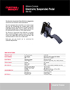
WM-542 Electronic Suspended Pedal

Curtiss Wrights Williams Controls WM-542 Electronic Suspended Pedal is designed for on-highway vehicle applications.


Description

Williams Controls WM-542 Electronic Suspended Pedal – Hall-Effect Electronic Throttle Control

The Williams Controls WM-542 Electronic Suspended Pedal is a rugged electronic accelerator control designed for commercial and industrial vehicle applications. Combining non-contact Hall-effect sensing technology with a lightweight composite construction, configurable electrical outputs and a suspended pedal architecture, the WM-542 provides Original Equipment Manufacturers with a versatile solution for communicating operator throttle demand to modern electronic vehicle control systems.

Designed as part of the Williams Controls electronic throttle control range, the WM-542 converts physical accelerator pedal movement into an electrical signal that can be interpreted by an engine control module, electronic fuel management system or compatible vehicle controller. This drive-by-wire approach eliminates the need for a conventional direct mechanical throttle connection between the operator pedal and the engine, providing greater flexibility when developing modern commercial and industrial vehicle platforms.

The WM-542 incorporates a Hall-effect non-contact sensor that can be programmed for analogue output and integrated switch functionality. Depending on the required configuration, the product family can also support contact or Pulse Width Modulation output sensors. Available output arrangements include Dual APS, Dual PWM, APS, PWM and APS/IVS, providing considerable flexibility when integrating the pedal with different electronic control architectures.

With a nominal 20-degree angular rotation, three-million full-travel cycle product life, IP67 sealed electronics and a broad -40°C to +85°C operating temperature range, the WM-542 is engineered to provide dependable throttle control in demanding commercial and industrial vehicle environments.

Designed for Commercial and Industrial Vehicle Applications

The Williams Controls WM-542 has been developed specifically for commercial and industrial vehicle applications where reliable electronic accelerator control is required. These applications can expose operator controls to frequent use, vibration, temperature variation, humidity, dust and other challenging environmental conditions throughout the working life of the vehicle.

Unlike accelerator components intended primarily for light-duty passenger vehicle use, industrial throttle controls may be required to operate for extended shifts and across substantial vehicle service lives. The WM-542 addresses these requirements through durable mechanical construction, non-contact electronic sensing and environmental protection designed around mobile equipment operation.

The product forms part of the wider Williams Controls suspended electronic pedal range, giving OEM engineers an alternative to floor-mounted accelerator controls. Suspended pedals can be particularly advantageous where clean floor access is required or where the architecture of the operator compartment is better suited to a pedal assembly supported from the vehicle structure above the floor.

Suspended Electronic Pedal Architecture

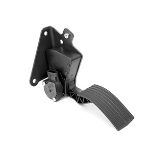
The suspended configuration of the WM-542 provides vehicle designers with a practical accelerator solution where mounting the primary pedal mechanism directly to the floor is undesirable. The pedal assembly uses a coated-steel mounting bracket together with a composite lever arm and body, creating a compact and durable operator control platform.

One of the important advantages of the WM-542 is its mechanical customisation capability. Both the lever arm and mounting bracket can be customised according to customer requirements. This allows OEM manufacturers to consider accelerator positioning as part of the complete operator environment rather than being restricted to one fixed mechanical arrangement.

Pedal placement can be influenced by numerous factors including seat position, brake pedal location, available footwell space, steering column geometry and surrounding operator controls. The adaptable architecture of the WM-542 provides engineers with greater freedom when integrating electronic accelerator control into different vehicle platforms.

A suspended pedal arrangement can also assist applications where maintaining relatively clear floor access is desirable. This characteristic can be valuable in commercial and industrial vehicles where dirt and debris may enter the operator compartment during normal use and straightforward floor cleaning is beneficial.

Non-Contact Hall-Effect Position Sensing

At the centre of the Williams Controls WM-542 is a Hall-effect non-contact position sensor. Hall-effect technology provides electronic measurement of accelerator movement without relying on the sliding electrical contacts traditionally used within potentiometer-based position sensors.

In a conventional contact-type potentiometer, pedal movement is measured by a mechanical wiper travelling across a resistive element. Repeated movement can gradually wear the contacting surfaces. This becomes an important consideration in accelerator pedal applications because the pedal may be operated millions of times during the service life of a commercial vehicle.

Hall-effect sensing determines position through changes in a magnetic field. The sensing electronics can therefore measure accelerator movement without requiring the primary electrical sensing elements to rub against one another during each pedal cycle.

This non-contact principle helps reduce electrical sensor wear and supports reliable position measurement over an extended service life. For commercial and industrial vehicle manufacturers, it provides a durable technology well suited to high-cycle operator controls such as electronic accelerator pedals.

Three Million Full-Travel Cycle Product Life

The WM-542 is rated for 3,000,000 full-travel cycles. This substantial cycle life demonstrates the pedal’s suitability for commercial and industrial vehicles where accelerator controls may be operated continuously throughout long working periods.

A full-travel cycle represents movement through the pedal’s operating range and return. Over the life of a high-utilisation vehicle, these movements can accumulate rapidly, particularly in applications involving frequent changes in speed or engine demand.

Long accelerator pedal life can provide important operational advantages. A durable throttle control can help reduce the likelihood of premature component replacement and the associated vehicle downtime, diagnostic work and maintenance labour.

The three-million-cycle mechanical rating works together with the non-contact Hall-effect sensing system to provide a throttle control platform designed around long-term vehicle operation.

20-Degree Nominal Angular Rotation

The Williams Controls WM-542 provides a nominal 20-degree angular rotation. This pedal movement allows the operator to progressively vary accelerator demand while providing the position sensor with the mechanical travel required to generate the corresponding electronic signal.

Pedal angular travel plays an important role in operator control. An accelerator must provide sufficient movement to allow progressive modulation of engine or motor demand without requiring excessive foot movement within the operator compartment.

The WM-542’s nominal 20-degree rotation provides a defined mechanical range that OEM engineers can incorporate into the overall cab and operator control design. The pedal position, lever geometry and surrounding clearances should be considered together to ensure unrestricted operation throughout the complete accelerator travel.

Configurable Electronic Output Options

Commercial and industrial vehicles use a wide variety of electronic engine and vehicle controllers. The WM-542 addresses these different architectures by supporting multiple electronic output configurations across the product family.

Available output signal options include Dual Accelerator Position Sensor (Dual APS), Dual Pulse Width Modulation (Dual PWM), single APS, single PWM and APS combined with an Idle Validation Switch (APS/IVS).

This range provides OEM engineers with flexibility when selecting a pedal for an existing controller or designing a new vehicle platform. Analogue APS outputs can provide proportional accelerator position information, while PWM configurations support electronic systems designed to interpret position through pulse width modulation.

The APS/IVS configuration provides proportional accelerator position information together with idle validation functionality for compatible control systems. The exact electrical configuration should always be selected according to the requirements of the associated engine, motor or vehicle controller.

Dual APS for Compatible Electronic Control Systems

Dual APS is an important configuration available within the WM-542 family. This arrangement provides two accelerator position signals that can be processed by a compatible electronic controller according to the system architecture developed by the vehicle manufacturer.

Modern electronic throttle systems may use multiple accelerator position channels as part of their signal monitoring and diagnostic strategy. The controller can compare or interpret these signals according to its programmed requirements.

For OEM engineers, the availability of Dual APS allows the WM-542 to be considered for vehicle platforms requiring multiple proportional accelerator position outputs while retaining the benefits of non-contact Hall-effect sensing.

Single and Dual PWM Configurations

The WM-542 can also be configured with PWM output technology. Pulse Width Modulation communicates accelerator position through changes in the duty cycle of an electrical signal rather than relying solely on a continuously varying analogue voltage.

Both single PWM and Dual PWM output options are available within the WM-542 product family. This provides additional compatibility with vehicle and engine controllers designed around PWM accelerator inputs.

The availability of analogue and PWM configurations within a common mechanical pedal platform can be particularly useful for manufacturers producing multiple vehicle variants. Different electronic architectures can potentially be accommodated while retaining a familiar accelerator assembly and installation concept.

5 V and 12 V to 24 V Operating Configurations

The Williams Controls WM-542 product family supports 5 V and 12 V to 24 V operating configurations, allowing the pedal to be adapted to different vehicle electrical and controller requirements.

Five-volt supplies are commonly used by electronic controllers for position sensor circuits, while 12 V and 24 V electrical architectures are widely used throughout commercial vehicles and industrial mobile equipment. The availability of different electrical configurations increases the versatility of the WM-542 for OEM integration.

The correct voltage specification must be selected for the intended controller and vehicle system. Engineers should verify the complete electrical requirements, including supply voltage, output signal, wiring and controller compatibility, rather than assuming that every WM-542 version is electrically interchangeable.

IP67 Sealed Electronics

Environmental protection is an important consideration for accelerator controls installed in commercial and industrial vehicles. Dust, moisture and other contaminants can enter the operator environment during normal operation, particularly in equipment used on worksites or in demanding industrial conditions.

The WM-542 product family incorporates electronics sealed to IP67 in accordance with IEC 60529. This rating provides protection against dust ingress and temporary water immersion under the conditions defined by the standard.

Protecting the position sensing electronics helps support dependable accelerator signal performance in environments where contamination may otherwise affect exposed electrical components. Combined with non-contact Hall-effect sensing, the IP67 electronics provide a robust foundation for demanding vehicle operation.

SAE J1113 Electromagnetic Compatibility

Modern vehicles contain an increasing number of electronic systems operating simultaneously. Engine controllers, motor controllers, transmission systems, communication networks, hydraulic controls, charging systems and auxiliary equipment can all contribute to the electromagnetic environment surrounding an electronic accelerator pedal.

The WM-542 electronics are highly resistant to electromagnetic interference and are compliant with SAE J1113. This is particularly important for an electronic throttle control because the accelerator signal must operate reliably alongside other electrical and electronic systems within the vehicle.

For OEM manufacturers, electromagnetic compatibility forms an important part of complete system integration. The SAE J1113 compliance of the WM-542 supports its use within modern electronically controlled commercial and industrial vehicle platforms.

Lightweight Composite Construction

A significant mechanical characteristic of the WM-542 is its use of composite materials. The throttle control incorporates a glass-filled nylon body and lever arm, while the mounting bracket is manufactured from coated steel.

The family-level technical specification identifies the main body as composite plastic, the mounting plate as coated steel and the treadle cover as composite plastic. This material combination provides a durable suspended pedal architecture while avoiding the heavier cast-aluminium construction used in some other Williams Controls accelerator products.

Composite materials can provide useful advantages for vehicle component design, including corrosion resistance and reduced component mass. The coated-steel mounting bracket provides the structural interface required for secure installation within the vehicle.

Customisable Lever Arm and Mounting Bracket

The ability to customise the lever arm and mounting bracket is one of the most useful characteristics of the WM-542 for OEM applications. Different commercial and industrial vehicles can have substantially different operator compartments, making a single fixed pedal geometry unsuitable for every installation.

Customisation allows the mechanical accelerator arrangement to be adapted according to customer requirements. This can assist manufacturers developing specialist vehicles or integrating the WM-542 into an existing cab where accelerator position is constrained by surrounding structures and controls.

Mechanical customisation should be considered alongside electrical configuration during the product selection process. By combining adaptable mounting with multiple output and voltage options, the WM-542 provides OEM engineers with flexibility on both sides of the accelerator interface.

Purpose-Built Electronic Throttle Control Platform

The Williams Controls WM-542 combines non-contact electronic sensing, configurable outputs, suspended pedal packaging and durable composite construction within a single electronic throttle control platform.

Its three-million full-travel cycle product life supports high-utilisation applications, while the nominal 20-degree angular rotation provides a practical accelerator operating range. IP67 sealed electronics and SAE J1113 electromagnetic compatibility contribute to dependable electronic performance, while the -40°C to +85°C operating capability supports use across a wide range of climatic conditions.

For commercial and industrial vehicle manufacturers requiring a configurable suspended electronic accelerator, the WM-542 provides a versatile Williams Controls solution capable of being adapted to different mechanical layouts and electronic control architectures.

Heavy-Duty Performance for Commercial and Industrial Vehicles

The Williams Controls WM-542 Electronic Suspended Pedal is engineered for the demanding operating conditions associated with commercial vehicles and industrial mobile equipment. Accelerator pedals are continuously exposed to operator input while also experiencing vibration, temperature variation, humidity, dust and other environmental influences generated by the vehicle and its surroundings.

The WM-542 addresses these challenges through a combination of robust composite construction, protected electronics and non-contact Hall-effect position sensing. Together, these characteristics create an electronic throttle control designed to provide dependable accelerator position information throughout demanding vehicle service.

Mechanical durability is particularly important in high-utilisation applications. Accelerator controls can accumulate millions of movements over their working life, while occasional forces considerably greater than normal pedal operation may also be encountered. The WM-542 incorporates mechanical strength and environmental resistance alongside its three-million-cycle rated product life to support these conditions.

667 N Static Load Capability

The Williams Controls WM-542 has a specified static load capability of 667 N. This rating demonstrates the mechanical strength of the pedal assembly and its ability to withstand loads beyond those normally required for routine accelerator operation.

Although accelerator pedals are designed to operate under controlled foot pressure, abnormal loads can occur during commercial service. An operator may inadvertently place excessive weight on the pedal, heavy work footwear can produce concentrated loading, or unusual movement within the cab can temporarily subject the accelerator assembly to additional force.

Mechanical strength under these circumstances is important because excessive deformation could influence pedal movement or the relationship between the lever and electronic position sensor. The WM-542’s specified static load capability therefore contributes to the overall durability of the accelerator assembly.

The correct mounting structure must also be capable of supporting the pedal and anticipated loads. OEM engineers should ensure the vehicle mounting arrangement is appropriately designed for the intended installation rather than relying solely on the strength of the accelerator component itself.

Three Million Full-Travel Cycles for Extended Service

The WM-542 is rated for 3,000,000 full-travel cycles, making it suitable for commercial and industrial vehicles where accelerator operation may occur repeatedly throughout long working shifts.

High-cycle performance is particularly relevant to applications involving frequent speed or engine-demand changes. Urban commercial vehicles, material handling equipment and specialist mobile machinery can all accumulate accelerator cycles rapidly compared with vehicles operating predominantly at constant speed.

The use of non-contact Hall-effect sensing complements the mechanical cycle rating. Because position measurement does not depend upon a conventional electrical wiper repeatedly moving across a resistive sensing track, a significant source of electrical contact wear is eliminated.

This combination of mechanical endurance and non-contact position measurement helps the WM-542 provide a dependable accelerator interface throughout extended vehicle service.

Random Broadband Vibration Testing up to 4 g

Vibration is unavoidable in commercial and industrial mobile equipment. Engine operation, driveline movement, hydraulic systems, road surfaces, industrial floors and uneven terrain can all transmit vibration through the vehicle structure to the accelerator assembly.

The Williams Controls WM-542 has been subjected to three-axis random broadband vibration testing up to 4 g, with testing performed for three hours on each axis. Testing across multiple axes is important because vibration within a real vehicle occurs in multiple directions rather than along a single predictable path.

Resistance to vibration supports the mechanical integrity of the suspended pedal assembly while also helping maintain the relationship between pedal movement and the electronic sensing system. The glass-filled nylon body and lever, coated-steel mounting bracket and protected electronics work together to create a throttle control suited to mobile applications.

For equipment operating on uneven roads, industrial surfaces or worksites, this vibration performance provides an important indication of the WM-542’s intended heavy-duty design environment.

Operating Across Extreme Temperatures

Commercial vehicles and industrial equipment may be required to operate across substantial temperature variations. Vehicles can encounter freezing winter conditions, high summer temperatures and elevated cabin temperatures generated by prolonged exposure to direct sunlight or surrounding machinery.

The WM-542 has a specified operating temperature range from -40°C to +85°C. Its storage temperature range is also specified from -40°C to +85°C.

This broad temperature capability supports the use of the WM-542 across diverse geographic and operating environments. It also provides vehicle manufacturers with greater flexibility when developing equipment intended for multiple markets or climatic regions.

Temperature performance is particularly important for an electronic accelerator because the position signal must remain dependable throughout the intended vehicle operating range. The engine, motor or vehicle controller relies upon accurate accelerator information to interpret the operator’s requested level of power.

High Humidity Resistance

High atmospheric humidity can present challenges for both mechanical and electronic components. Commercial equipment operating in tropical climates, coastal regions or other moisture-rich environments may experience prolonged exposure to elevated relative humidity.

The WM-542 is specified for humidity testing at 95% relative humidity for 120 hours across temperatures from 27°C to 75°C. This testing complements the environmental protection provided by the sealed electronic assembly.

Resistance to humidity helps support reliable operation where moisture may otherwise contribute to corrosion or deterioration of inadequately protected components. The combination of protected electronics, composite materials and coated metal components contributes to the WM-542’s suitability for demanding vehicle environments.

Sand and Dust Testing to SAE J1455

Dust and airborne particulate contamination are common challenges in commercial and industrial applications. Construction sites, agricultural environments, mining operations, warehouses, ports, unsealed roads and manufacturing facilities can all expose vehicle controls to substantial levels of dust.

The Williams Controls WM-542 has been tested for sand and dust exposure in accordance with SAE J1455. This environmental testing is particularly relevant to accelerator controls because the operator footwell can collect contamination introduced by footwear and normal vehicle access.

The WM-542’s IP67 sealed electronics provide additional protection against dust ingress. Combined with Hall-effect non-contact sensing, this helps protect the electronic position measurement system from the environmental conditions encountered during everyday commercial operation.

IP67 Protection for Electronic Components

The electronics of the WM-542 are sealed to IP67 in accordance with IEC 60529. This level of protection provides complete protection against dust ingress and protection against temporary water immersion under the conditions specified by the standard.

Environmental sealing is important because accelerator position information forms a critical input to the vehicle’s electronic control system. Moisture or contamination affecting the sensor electronics could compromise dependable signal generation.

By protecting the electronic sensing components within the accelerator assembly, the WM-542 provides a more robust platform for applications where dust and moisture may be encountered during normal vehicle use.

It is important to distinguish the general WM-542 family specification from individual customer-specific variants. Environmental ratings and electrical characteristics should always be confirmed against the exact Williams Controls part number when specifying a pedal for a particular application.

Reliable Operation in Complex Electronic Environments

Modern commercial vehicles can incorporate numerous electrical and electronic systems operating simultaneously. Engine management systems, electric motor controllers, transmission controls, hydraulic systems, telematics, charging systems, communication networks and auxiliary equipment can all contribute to the vehicle’s electromagnetic environment.

The WM-542 electronics are designed for high resistance to electromagnetic interference and comply with SAE J1113 requirements. This supports reliable accelerator position sensing alongside the other electronic systems installed within the vehicle.

Electromagnetic compatibility is an important consideration for an electronic throttle control because the accelerator signal must accurately represent operator demand. The controller receiving this signal can then process it according to the programmed vehicle control strategy.

Understanding APS Output

An Accelerator Position Sensor, or APS, provides proportional information corresponding to the position of the accelerator pedal. As the operator moves the WM-542 through its travel, the electronic sensor produces an output that can be interpreted by the compatible engine or vehicle controller.

APS configurations are useful in electronic throttle systems where the controller is designed to receive an analogue representation of accelerator position. The relationship between pedal movement and the required output is determined by the specific configuration selected for the application.

The exact electrical characteristics should therefore be confirmed against the applicable Williams Controls documentation and controller requirements. Engineers should not assume that all WM-542 APS configurations use identical output characteristics.

Dual APS Electronic Architecture

The WM-542 is also available with Dual APS outputs. In this arrangement, two accelerator position signals are provided for processing by a compatible electronic controller.

Dual-channel architectures may be used by vehicle manufacturers as part of the electronic system’s monitoring and diagnostic strategy. The controller can evaluate the available position information according to the electrical architecture and software logic developed for the vehicle.

The availability of Dual APS allows the WM-542 to support more sophisticated electronic throttle systems while retaining the durability advantages of non-contact Hall-effect position sensing.

APS with Idle Validation Switch

The APS/IVS configuration combines proportional accelerator position information with Idle Validation Switch functionality. This provides the compatible vehicle controller with accelerator position information together with a discrete indication associated with the pedal’s idle condition.

Some engine management architectures are specifically designed around this combination of signals. Integrating APS and IVS functionality within the accelerator assembly can provide an effective operator input solution for these systems.

As with other WM-542 configurations, the specific electrical interface must be matched to the requirements of the controller. Supply voltage, signal characteristics, switch operation and wiring should all be confirmed before selecting a particular part number.

PWM Accelerator Position Output

Pulse Width Modulation provides another method of communicating accelerator position electronically. Instead of representing position solely through a changing analogue voltage, PWM uses variations in the duty cycle of a pulsed electrical signal.

The WM-542 product family supports both single PWM and Dual PWM output configurations. This allows the pedal to interface with compatible controllers designed to receive accelerator position information in PWM format.

The availability of APS and PWM technologies within the same product family broadens the range of electronic architectures that can be supported by the WM-542. This can be particularly useful for OEMs using different controllers across several vehicle models.

Supporting 5 V, 12 V and 24 V Vehicle Architectures

The WM-542 family supports 5 V and 12 V to 24 V configurations depending on the selected electronic arrangement. This provides flexibility for integration across a range of commercial and industrial vehicle electrical systems.

Five-volt sensor supplies are widely used by electronic control modules for position sensing, while 12 V and 24 V electrical systems are common throughout commercial vehicles and heavy mobile equipment.

OEM engineers should select the appropriate WM-542 configuration according to the electrical architecture of the vehicle and the requirements of the receiving controller. Correct voltage compatibility is essential, and a pedal intended for one supply arrangement should not be assumed to be suitable for another.

Composite Construction for Mobile Equipment

The WM-542 uses engineered composite materials for its main body and lever assembly. Glass-filled nylon provides a useful combination of strength, corrosion resistance and reduced mass for mobile equipment applications.

The mounting interface incorporates coated steel, providing structural support where the accelerator assembly attaches to the vehicle. The combination of composite and coated-metal components allows the WM-542 to achieve a robust mechanical structure without relying upon the heavier cast-metal body used by some other suspended pedal designs.

This construction also differentiates the WM-542 from the WM-540. While both products provide suspended electronic throttle control, their mechanical architecture, load capabilities and product life ratings differ, allowing engineers to select the product best suited to the requirements of the intended vehicle.

Customisation for OEM Installation

One of the significant benefits of the Williams Controls WM-542 is its ability to accommodate customised lever arm and mounting bracket requirements. Commercial and industrial vehicle cabs vary substantially in their seating positions, firewall geometry and available operator footwell space.

Rather than forcing every installation around one fixed accelerator geometry, the WM-542 platform can be adapted to suit customer requirements. This flexibility can simplify integration into specialist vehicles and support manufacturers developing several related equipment platforms.

Mechanical customisation should be coordinated with electrical configuration during the design process. Pedal location, lever geometry, full-travel clearance, controller compatibility, output format and supply voltage all contribute to successful accelerator integration.

OEM System Integration Considerations

Correct integration of the WM-542 requires more than selecting a physically suitable accelerator pedal. The complete electronic throttle system should be considered to ensure that the pedal and receiving controller are compatible.

Engineers should confirm the required supply voltage, output architecture, signal characteristics, wiring arrangement and any idle validation requirements. The selected mechanical configuration should also provide appropriate pedal placement and unrestricted movement throughout the nominal 20-degree travel.

The mounting structure should be designed to support the pedal under expected operating and abnormal loads, while surrounding controls should provide sufficient clearance to prevent interference with accelerator movement.

Environmental conditions should also form part of the selection process. Temperature, moisture, dust, vibration and expected operating cycles should be compared with the applicable WM-542 specifications before the product is incorporated into a vehicle design.

A Versatile Electronic Suspended Pedal Platform

The Williams Controls WM-542 provides a strong combination of mechanical durability, environmental resistance and electronic flexibility. Its 667 N static-load capability, three-million-cycle product life and 4 g three-axis vibration testing support demanding commercial and industrial applications.

A -40°C to +85°C temperature range, humidity resistance, SAE J1455 sand and dust testing and IP67 sealed electronics further strengthen its suitability for mobile equipment operating in challenging conditions.

At the electronic level, APS, Dual APS, PWM, Dual PWM and APS/IVS configurations provide flexibility for integration with different engine, motor and vehicle controllers. Combined with 5 V and 12 V to 24 V configurations, Hall-effect non-contact sensing and customisable mechanical arrangements, the WM-542 provides OEM manufacturers with a versatile suspended accelerator platform for modern electronically controlled vehicles.

Electronic Accelerator Control for Modern Commercial Vehicles

The Williams Controls WM-542 Electronic Suspended Pedal provides an adaptable accelerator interface for commercial and industrial vehicles using electronically controlled power systems. Its suspended architecture, non-contact Hall-effect sensing, configurable electronic outputs and lightweight composite construction allow the pedal to support a broad range of OEM vehicle designs.

Modern electronic throttle systems require dependable communication between the operator and the vehicle controller. Rather than mechanically controlling engine power through a traditional cable or linkage, the WM-542 measures pedal position electronically and provides the corresponding signal to a compatible engine, motor or vehicle control system.

This electronic approach gives vehicle manufacturers greater flexibility when developing operator environments and powertrain architectures. Pedal position can be selected according to cab geometry and operator requirements, while the electrical configuration can be matched to the controller used within the vehicle.

Commercial Truck Applications

The WM-542 is suitable for commercial truck applications requiring a suspended electronic accelerator pedal. Trucks can accumulate substantial operating hours and may experience continuous vibration, temperature variation and repeated accelerator operation throughout their working life.

With a rated life of three million full-travel cycles, the WM-542 is engineered around the demands of commercial service. Hall-effect non-contact sensing complements this mechanical durability by measuring accelerator position without relying on conventional sliding electrical sensing contacts.

The availability of different electronic outputs is particularly valuable for commercial vehicle manufacturers. APS, Dual APS, PWM, Dual PWM and APS/IVS configurations allow the pedal to support different compatible engine management architectures, while 5 V and 12 V to 24 V options provide additional electrical flexibility.

Bus and Passenger Transport Applications

Bus and passenger transport vehicles can place significant cycle demands on accelerator controls. Urban buses may experience frequent acceleration and deceleration throughout each route, creating a high number of pedal movements over the service life of the vehicle.

The WM-542’s three-million-cycle product life and non-contact Hall-effect sensing provide a strong foundation for these high-utilisation applications. The suspended pedal architecture can also provide useful packaging advantages within driver compartments where floor space, control positioning and accessibility are important design considerations.

Customisable lever arm and mounting bracket arrangements allow the pedal geometry to be adapted to suit specific vehicle layouts. This gives OEM engineers additional flexibility when positioning the accelerator relative to the driver’s seat, brake pedal, steering system and surrounding controls.

Hybrid and Electrified Vehicle Applications

Electronic accelerator pedals are also an important operator interface within hybrid and electrified vehicle architectures. In these applications, pedal position can be interpreted by a vehicle control system that manages power demand according to the operating strategy of the complete drivetrain.

The WM-542 provides electronic position information that can be integrated with compatible control architectures. Its configurable APS and PWM output options provide OEM engineers with flexibility when developing vehicles using different controller technologies.

The lightweight composite construction of the WM-542 can also be advantageous where manufacturers are seeking to manage component mass throughout the vehicle. Although accelerator pedal weight represents only one part of the complete vehicle design, the use of engineered composite materials provides a durable alternative to heavier cast-metal accelerator structures.

Crane and Specialist Mobile Equipment Applications

Specialist mobile machinery such as cranes can require precise control over engine or power demand while operating in environments characterised by vibration, dust and substantial daily utilisation. An electronic accelerator used in these applications must provide dependable position information while withstanding the environmental conditions associated with mobile equipment.

The WM-542 combines Hall-effect non-contact sensing with IP67 sealed electronics, multi-axis vibration resistance and SAE J1455 sand and dust testing. These characteristics support its use in demanding mobile applications where reliable electronic throttle control is required.

The ability to customise the lever arm and mounting bracket can be especially useful in specialist machinery. Operator compartments in cranes and purpose-built mobile equipment can differ significantly from conventional truck cabs, making mechanical flexibility an important consideration during accelerator selection.

Material Handling Equipment

Material handling vehicles can experience intensive duty cycles involving repeated changes in speed and engine or motor demand. Frequent manoeuvring in warehouses, yards, ports and industrial facilities can generate large numbers of accelerator movements during each working shift.

The WM-542’s three-million-cycle design life makes it suitable for applications where repeated accelerator operation is expected. Non-contact Hall-effect sensing further supports long-term performance by eliminating the sliding electrical contact mechanism associated with conventional potentiometer sensing.

Environmental durability is equally important. Dust and debris can be introduced into the operator compartment through footwear and everyday equipment operation. The WM-542’s IP67 sealed electronics and SAE J1455 sand and dust testing help provide the environmental protection required for these demanding applications.

Benefits of Lightweight Composite Construction

The mechanical construction of the WM-542 is an important point of difference within the Williams Controls suspended pedal range. The main body and lever incorporate engineered composite materials, including glass-filled nylon, while a coated-steel mounting bracket provides the structural interface with the vehicle.

Composite construction provides a useful combination of mechanical strength, corrosion resistance and reduced component mass. This makes the WM-542 an attractive solution for manufacturers seeking a robust suspended accelerator without requiring the heavier cast-metal architecture used by some alternative pedal designs.

The material selection also complements the product’s environmental capabilities. Corrosion-resistant composite components are well suited to commercial and industrial vehicle environments where moisture, humidity and contamination may be encountered throughout the working life of the equipment.

Advantages of Suspended Pedal Installation

A suspended electronic pedal can provide several packaging advantages compared with a floor-mounted accelerator assembly. By supporting the primary pedal mechanism from the vehicle structure above the floor, engineers can maintain a relatively clear operator footwell and position the accelerator according to the architecture of the cab.

Clearer floor access can assist with cleaning in commercial and industrial vehicles where dirt and debris are regularly introduced through operator footwear. It may also provide additional flexibility for routing other vehicle components through or beneath the floor structure.

The WM-542 expands on these advantages by allowing customisation of the lever arm and mounting bracket. This gives OEM engineers greater control over the final treadle position and mechanical relationship between the accelerator and surrounding operator controls.

WM-542 Compared with the Williams Controls WM-540

The Williams Controls WM-542 and WM-540 are both electronic suspended accelerator pedals, but they are designed around different mechanical characteristics. Understanding these differences can help OEM engineers determine which platform is better suited to a particular vehicle.

The WM-542 uses a lightweight composite body and lever arrangement and provides a nominal 20-degree angular rotation. It is rated for three million full-travel cycles and has a specified static-load capability of 667 N. Its electronics are IP67 sealed, and the product family supports APS, Dual APS, PWM, Dual PWM and APS/IVS configurations.

The WM-540 uses a more substantial cast-aluminium housing and steel lever architecture. It provides 19.5 degrees of angular rotation, a five-million-cycle rated product life and a higher 1500 N static-load capability. Like the WM-542, its electronics are specified to IP67 and multiple electronic output configurations are available.

The choice between the two products should therefore be based on the requirements of the application. Where particularly high mechanical loading and extended cycle life are priorities, the WM-540 may offer advantages. Where a lighter composite suspended pedal with adaptable mechanical geometry is preferred, the WM-542 can provide an excellent solution.

Flexible OEM Platform Standardisation

The configurable nature of the WM-542 can provide opportunities for OEM platform standardisation. Vehicle manufacturers frequently develop several models around related cab structures while using different engines, controllers or electrical architectures.

The availability of different WM-542 output configurations allows manufacturers to retain a common accelerator concept while selecting electronics appropriate to individual vehicle variants. Customisable lever and bracket arrangements provide similar flexibility on the mechanical side of the installation.

Reducing unnecessary component variation can simplify procurement, manufacturing documentation, technician training and aftermarket parts management. The extent to which standardisation is possible will depend on the requirements of each vehicle, but the flexibility of the WM-542 provides a useful starting point for OEM engineering programmes.

Selecting the Correct WM-542 Configuration

Correct specification of a Williams Controls WM-542 requires consideration of both the mechanical installation and the electronic control architecture. Engineers should first determine the required pedal position, mounting geometry and clearance throughout the complete nominal 20-degree pedal travel.

The expected mechanical loads and environmental conditions should also be reviewed. The WM-542’s 667 N static-load capability, IP67 electronics, temperature range, vibration performance and sand and dust testing should be compared with the requirements of the intended vehicle.

Electrical selection should include the required supply voltage and output architecture. APS, Dual APS, PWM, Dual PWM and APS/IVS configurations serve different controller requirements, and the exact electrical characteristics of the selected part number must be verified before integration.

OEM engineers should also confirm wiring and connector requirements for the specific configuration being considered. Individual customer-specific versions of the WM-542 may differ from the general product-family specification, making exact part-number identification particularly important.

Replacement WM-542 Pedal Selection

When replacing an existing WM-542 Electronic Suspended Pedal, the model family designation alone should not be used to determine compatibility. Different WM-542 configurations may incorporate different electrical outputs, supply requirements, mechanical arrangements or customer-specific characteristics.

The original Williams Controls part number should therefore be identified wherever possible. Electrical output, operating voltage, connector arrangement, lever geometry and mounting details should then be compared with the proposed replacement.

This is especially important for electronic accelerator controls because a pedal that appears mechanically similar may not provide the electrical signals expected by the existing controller. Correct identification helps ensure that the replacement component matches both the mechanical and electronic requirements of the vehicle.

WM-542 Product Family and Customer-Specific Variants

The WM-542 is available as a configurable product family, and individual customer-specific versions may incorporate characteristics tailored to a particular vehicle or control system. This is an important consideration when interpreting technical specifications or selecting replacement components.

General WM-542 family information describes the broader capabilities of the platform, including multiple output and voltage options. A specific production part number may represent only one combination of these available characteristics.

For this reason, engineers, maintenance organisations and equipment owners should verify the exact configuration required for their application. Product-family information is useful for initial selection, but the final specification should always be confirmed against the applicable part number and technical documentation.

Why Choose the Williams Controls WM-542 Electronic Suspended Pedal?

The Williams Controls WM-542 combines several characteristics that make it a versatile electronic accelerator solution for commercial and industrial vehicles. Its suspended architecture provides useful installation flexibility, while customisable lever and mounting arrangements allow the pedal geometry to be adapted to different operator environments.

Non-contact Hall-effect sensing provides electronic accelerator position measurement without conventional sliding sensing contacts. A three-million-cycle rated product life supports high-utilisation applications, while the composite body and lever provide a strong, corrosion-resistant and relatively lightweight mechanical structure.

Environmental characteristics including IP67 sealed electronics, SAE J1113 electromagnetic compatibility, SAE J1455 sand and dust testing, humidity resistance, multi-axis vibration performance and a -40°C to +85°C temperature range further support demanding commercial operation.

The availability of APS, Dual APS, PWM, Dual PWM and APS/IVS configurations provides additional flexibility for modern electronic vehicle systems. Together, these characteristics allow the WM-542 to support a broad range of OEM throttle control requirements.

Williams Controls WM-542 from Control Devices

For Australian OEMs, vehicle manufacturers, system integrators and equipment service organisations requiring a configurable electronic suspended accelerator, the Williams Controls WM-542 provides a versatile combination of non-contact sensing, environmental durability and adaptable mechanical design.

Control Devices can assist with the selection of an appropriate WM-542 configuration according to the requirements of the application. Important considerations include operating voltage, electronic output type, controller compatibility, lever geometry, mounting arrangement and environmental conditions.

Correct product selection is particularly important when replacing an existing accelerator pedal or integrating the WM-542 into a new vehicle platform. Confirming the exact electrical and mechanical requirements helps ensure that the selected pedal is appropriate for the intended electronic control system and installation.

Williams Controls WM-542 – Versatile Non-Contact Electronic Suspended Pedal

The Williams Controls WM-542 Electronic Suspended Pedal provides a durable and adaptable operator control for electronically controlled commercial and industrial vehicles. Its Hall-effect non-contact sensing technology, nominal 20-degree angular rotation and three-million-cycle rated product life provide a strong foundation for reliable accelerator position control.

With IP67 sealed electronics, broad temperature capability, vibration resistance and SAE J1455 sand and dust testing, the WM-542 is engineered for operation in demanding mobile environments. Its lightweight composite construction and customisable mechanical arrangement provide additional flexibility when integrating the pedal into different vehicle platforms.

Multiple APS and PWM output configurations, combined with 5 V and 12 V to 24 V options, allow the WM-542 platform to support a variety of compatible electronic control architectures. For OEM manufacturers seeking a configurable suspended electronic accelerator with proven Williams Controls technology, the WM-542 provides a practical solution for modern commercial vehicles and specialist mobile equipment.

For the full range of Custiss Wright products

Follow us on Facebook

data sheet

Electronic Throttle Controls Brochure