Description
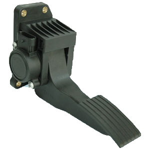
Williams Controls WM-546 Electronic Suspended Pedal – Compact Fixed-Mount Hall-Effect Throttle Control
The Williams Controls WM-546 Electronic Suspended Pedal is a compact, fixed-mount electronic accelerator designed for commercial vehicle applications where efficient packaging, dependable throttle control and a cost-effective pedal solution are important considerations. Combining a lightweight all-plastic construction with non-contact Hall-effect sensing technology, integrated firewall mounting and configurable electronic output options, the WM-546 provides Original Equipment Manufacturers with a practical solution for modern electronically controlled vehicle platforms.
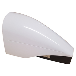
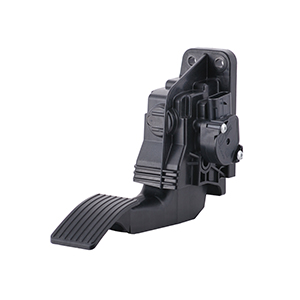
Unlike adjustable suspended pedal systems designed around multiple lever and bracket configurations, the WM-546 incorporates a fixed-mounting architecture. The all-plastic housing features a three-hole bolt pattern for mounting directly to the vehicle firewall, while the foot pad is moulded as an integral part of the pedal lever arm. This integrated construction creates a compact accelerator assembly with fewer separate structural components and a straightforward mechanical installation concept.
The WM-546 is equipped with a Hall-effect non-contact sensor capable of providing electronic accelerator position information to a compatible vehicle or engine control system. The sensor can be programmed for analogue output and integrated switch functionality, while the product can also be offered with contact or Pulse Width Modulation output sensing configurations. Available signal arrangements include Dual APS, APS/IVS, APS/IVS/IVS and Dual PWM, providing flexibility for different electronic throttle architectures.
With a rated product life of four million full-travel cycles, 19° ± 2° angular rotation, 1500 N static-load capability and IP67 sealed electronics, the WM-546 combines compact packaging with the durability required for demanding commercial vehicle operation.
Designed for Commercial Vehicle Applications
The Williams Controls WM-546 has been developed for commercial vehicle applications where accelerator components must provide reliable performance throughout substantial operating periods. Commercial vehicles can accumulate significant working hours and may expose operator controls to repeated pedal movements, vibration, temperature variation, humidity, dust and other environmental influences.
The WM-546 addresses these requirements through a combination of durable mechanical construction and proven electronic sensing technology. Its compact fixed-mounting architecture is particularly relevant where vehicle manufacturers require an electronic suspended pedal without the additional mechanical complexity associated with highly customisable accelerator assemblies.
This makes the WM-546 an attractive solution for OEM manufacturers seeking to balance durability, packaging efficiency and overall system cost. The design provides the core functionality required from an electronic accelerator while maintaining a straightforward mechanical architecture suitable for integration into commercial vehicle operator environments.
Compact Fixed-Mounting Suspended Pedal Design
One of the defining characteristics of the WM-546 is its fixed-mounting suspended pedal architecture. The housing incorporates a three-hole bolt pattern specifically designed for mounting to the vehicle firewall, providing a direct and compact installation arrangement.
Fixed mounting can offer several advantages where the vehicle platform has a defined accelerator location. Rather than requiring adjustable brackets or customised lever assemblies, the WM-546 can be incorporated into a vehicle structure designed around its established mounting geometry.
This approach can simplify the mechanical integration process for production vehicles. Once the required accelerator position and firewall mounting structure have been established, the same pedal architecture can be incorporated consistently across compatible vehicle builds.
The compact construction can also be beneficial where available space within the operator compartment is limited. Accelerator pedals must coexist with brake controls, steering components, wiring, cab structures and other operator interfaces, making efficient use of available footwell space an important part of vehicle design.
Three-Hole Firewall Mounting Pattern
The WM-546 housing incorporates a three-hole bolt pattern for mounting the accelerator assembly to the vehicle firewall. This integrated mounting arrangement is an important distinction from suspended pedals that use separate or highly configurable mounting brackets.
For OEM vehicle manufacturers, a defined mounting pattern can simplify the design of the corresponding firewall structure. Mounting locations can be incorporated into the cab design during the engineering stage, providing repeatable accelerator positioning during production assembly.
Correct firewall construction remains an important consideration. The vehicle mounting structure must provide sufficient support for normal accelerator operation and the mechanical loads that may be transmitted through the pedal assembly.
Pedal positioning should also be considered together with the driver’s seat, brake pedal, steering system and surrounding controls. Appropriate placement helps provide comfortable accelerator operation while ensuring sufficient clearance throughout the complete pedal travel.
Integral Foot Pad and Pedal Lever Arm
The foot pad of the WM-546 is moulded as an integral part of the pedal lever arm. This integrated design contributes to the compact and cost-effective architecture of the accelerator assembly by reducing the need for separate treadle and lever components.
Integrating these elements also creates a direct mechanical relationship between the operator contact surface and the accelerator mechanism. Pedal movement is transferred through the moulded lever structure to the position sensing system, where the operator’s requested accelerator position is converted into an electronic signal.
The foot treadle and body are manufactured from glass-filled Nylon 66. This engineered material provides a combination of mechanical strength, corrosion resistance and reduced component mass appropriate for commercial vehicle control applications.
Non-Contact Hall-Effect Position Sensing
At the heart of the Williams Controls WM-546 is a Hall-effect non-contact position sensor. This technology allows accelerator position to be measured electronically without relying on conventional sliding electrical sensing contacts.
Traditional potentiometer-based position sensors generally use a mechanical wiper moving across a resistive track. Each accelerator movement produces physical contact between these sensing components, meaning repeated operation can gradually contribute to electrical wear.
Hall-effect technology operates differently. Accelerator movement changes the relationship of a magnetic field within the sensor, allowing the electronics to determine pedal position without requiring the primary sensing elements to rub against one another.
This non-contact principle is particularly valuable in commercial accelerator applications because pedals can experience millions of movements during the working life of a vehicle. Reducing electrical contact wear supports long-term position measurement and complements the mechanical durability of the complete WM-546 assembly.
Four Million Full-Travel Cycle Product Life
The WM-546 is rated for 4,000,000 full-travel cycles. This substantial cycle capability positions the pedal between several other products within the Williams Controls suspended electronic pedal range and demonstrates its suitability for high-utilisation commercial vehicle applications.
A full-travel cycle represents movement of the accelerator through its operating range and return. In applications involving frequent changes in vehicle speed or engine demand, these cycles can accumulate rapidly throughout each working shift.
The four-million-cycle rating provides OEM manufacturers with a useful indication of the pedal’s intended durability. Combined with Hall-effect non-contact sensing, it creates an accelerator platform designed around extended commercial vehicle operation.
Long component life can also contribute to reduced vehicle downtime. Accelerator pedal replacement can involve diagnostic work, parts procurement and maintenance labour, making durable operator controls valuable for fleet operators and equipment owners seeking dependable vehicle availability.
19° ± 2° Angular Rotation
The Williams Controls WM-546 provides 19° ± 2° of angular pedal rotation. This operating range provides the physical accelerator travel required for the operator to progressively communicate changes in engine or vehicle power demand.
Pedal travel is an important aspect of accelerator design because it influences operator control and the mechanical space required around the pedal. The accelerator should provide sufficient movement for progressive throttle modulation while remaining compact enough for practical integration into the vehicle footwell.
The specified angular rotation allows OEM engineers to account for the complete pedal movement when designing the surrounding operator environment. Adequate clearance should be maintained throughout the travel to prevent interference with floor structures, trim, adjacent controls or other vehicle components.
Progressive Pedal Operating Force
In addition to its defined angular travel, the WM-546 provides progressive operating resistance as the accelerator moves from its neutral position towards full travel. The specified operating force is 25 N at neutral and 37 N at full travel.
This increase in force provides the operator with progressive mechanical feedback as accelerator demand increases. Appropriate pedal resistance is important because it allows the driver to control accelerator movement while maintaining a natural physical relationship between foot movement and requested vehicle response.
Progressive resistance can be particularly beneficial during applications requiring small changes in accelerator demand. Rather than providing an excessively light pedal throughout the complete travel, the increasing force helps create a controlled accelerator feel.
1500 N Static-Load Capability
Despite its compact all-plastic architecture, the WM-546 has a specified static-load capability of 1500 N. This demonstrates substantial mechanical strength for a commercial vehicle accelerator assembly.
Normal accelerator operation requires considerably less force than this static-load rating. However, vehicle pedals can occasionally be subjected to abnormal loads caused by operator movement, heavy footwear or unintended pressure within the footwell.
The ability to withstand significant static loading contributes to the mechanical robustness of the WM-546. This is particularly notable given the use of glass-filled Nylon 66 for the pedal and housing, demonstrating how engineered polymer construction can provide both reduced mass and substantial structural capability.
Dual APS Electronic Output
The WM-546 is available with Dual Accelerator Position Sensor output. Dual APS provides two accelerator position signals for use by a compatible electronic vehicle or engine controller.
Multiple position signals can be incorporated into the monitoring and diagnostic strategy of an electronic throttle system. The receiving controller processes these signals according to the electrical architecture and software developed by the vehicle or engine manufacturer.
The availability of Dual APS makes the WM-546 suitable for electronic control systems requiring multiple proportional accelerator position signals while retaining the benefits of Hall-effect non-contact sensing.
APS with Idle Validation Switch
The WM-546 can also be configured with Accelerator Position Sensor and Idle Validation Switch functionality, identified as APS/IVS. This arrangement combines proportional accelerator position information with a discrete switch signal associated with the pedal’s idle condition.
Idle validation is used by compatible electronic control architectures as an additional indication of accelerator state. The exact way this information is interpreted depends on the controller and vehicle system in which the pedal is installed.
The WM-546 also supports an APS/IVS/IVS configuration, providing an additional idle validation switch arrangement for systems designed around this signal architecture.
When specifying the pedal, OEM engineers should confirm the exact electrical configuration required by the receiving controller rather than assuming that different WM-546 output versions are interchangeable.
Dual PWM Output Configuration
Dual Pulse Width Modulation is another available output configuration for the Williams Controls WM-546. PWM provides an alternative method of communicating accelerator position to compatible electronic controllers.
Rather than representing accelerator position solely through a varying analogue voltage, PWM communicates information through changes in the duty cycle of a pulsed electrical signal. Electronic controllers designed around PWM inputs can interpret these changes as corresponding accelerator positions.
The availability of Dual PWM alongside Dual APS and APS/IVS configurations broadens the range of electronic throttle architectures that can be supported by the WM-546 platform.
IP67 Sealed Electronics
Commercial vehicle controls may encounter dust, moisture and contamination throughout normal service. The operator footwell is particularly susceptible to contaminants introduced through footwear, open doors and everyday vehicle operation.
The electronics within the WM-546 are sealed to IP67 in accordance with IEC 60529. This provides protection against dust ingress and temporary water immersion under the conditions defined by the standard.
Protecting the accelerator position sensing electronics helps support reliable signal generation in demanding operating environments. The environmental sealing complements the non-contact Hall-effect sensing system and corrosion-resistant characteristics of the engineered plastic construction.
SAE J1113 Electromagnetic Compatibility
Modern commercial vehicles incorporate numerous electronic systems operating simultaneously. Engine management, transmission controls, communications, charging systems, telematics and auxiliary equipment can all contribute to the electromagnetic environment surrounding an accelerator sensor.
The WM-546 electronics are highly resistant to electromagnetic interference and comply with SAE J1113 requirements. This supports dependable operation when the accelerator is integrated alongside other electronic vehicle systems.
Electromagnetic compatibility is particularly important for electronic throttle controls because the accelerator position signal forms part of the communication between the operator and the vehicle control system. Robust electronic design helps maintain reliable signal performance within complex commercial vehicle electrical environments.
Glass-Filled Nylon 66 Construction
The WM-546 uses glass-filled Nylon 66 for both the foot treadle and body. This all-plastic construction is central to the product’s compact and cost-effective design philosophy.
Glass reinforcement improves the mechanical properties of the nylon material, allowing the accelerator structure to provide the strength required for demanding vehicle operation while retaining the corrosion resistance and reduced mass associated with engineered polymers.
The integrated construction also reduces the number of separate structural components required within the pedal assembly. This distinguishes the WM-546 from heavier suspended accelerator designs based around cast-metal housings and separate steel lever structures.
Compact and Cost-Effective Electronic Throttle Control
The Williams Controls WM-546 brings together the characteristics required from a modern commercial vehicle accelerator within a compact fixed-mounting platform. Its three-hole firewall mounting pattern and integral moulded pedal structure provide a straightforward mechanical architecture, while Hall-effect non-contact sensing delivers electronic accelerator position measurement without conventional sliding sensing contacts.
A four-million-cycle rated product life, 1500 N static-load capability and progressive 25 N to 37 N operating force provide substantial mechanical performance. IP67 sealed electronics and SAE J1113 electromagnetic compatibility further support reliable operation within demanding commercial vehicle environments.
With Dual APS, APS/IVS, APS/IVS/IVS and Dual PWM output options, the WM-546 can support a variety of compatible electronic throttle architectures. For OEM manufacturers requiring a compact, durable and cost-effective fixed-mount electronic suspended pedal, the WM-546 provides a highly practical solution within the Williams Controls electronic throttle control range.
Engineered for Demanding Commercial Vehicle Environments
The Williams Controls WM-546 Electronic Suspended Pedal is designed to operate within the challenging environments encountered by commercial vehicles and industrial mobile equipment. Accelerator controls can experience continuous vibration, repeated operator input, temperature extremes, humidity, dust and contamination throughout the working life of a vehicle.
For an electronic throttle pedal, environmental durability is particularly important because the accelerator forms the primary interface between operator demand and the vehicle’s electronic control system. Reliable mechanical movement must be combined with dependable electronic position sensing to provide consistent accelerator information to the compatible engine or vehicle controller.
The WM-546 addresses these requirements through a combination of glass-filled Nylon 66 construction, non-contact Hall-effect sensing, IP67 sealed electronics and environmental qualification for vibration, temperature, humidity, sand and dust exposure.
Three-Axis Random Broadband Vibration Testing
Vibration is an unavoidable characteristic of commercial vehicle operation. Engine movement, driveline vibration, road surfaces, suspension movement, hydraulic systems and auxiliary equipment can all transmit vibration through the vehicle structure and into the operator controls.
The WM-546 is specified for random broadband vibration testing up to 4 g. Testing is conducted across three axes for three hours on each axis, providing a demanding assessment of the accelerator assembly’s ability to withstand multidirectional vibration.
Testing across three axes is particularly relevant because vibration within a working vehicle does not occur in only one direction. Longitudinal, lateral and vertical forces can all act upon the pedal assembly as the vehicle operates.
Vibration resistance supports both the mechanical and electronic integrity of the WM-546. The fixed-mount housing, integral pedal lever and protected sensing electronics must continue to function together despite repeated vibrational loading throughout the vehicle’s service life.
Benefits of Fixed Mounting in High-Vibration Applications
The fixed-mounting architecture of the WM-546 provides a straightforward mechanical interface between the accelerator and vehicle structure. A three-hole bolt pattern allows the housing to be secured directly to the vehicle firewall, reducing the requirement for separate mounting brackets or additional adjustable structures.
For applications exposed to regular vibration, a well-engineered mounting interface is essential. The vehicle firewall and associated structure should provide sufficient rigidity to support the accelerator without excessive movement or flexing.
Correct fastener selection, mounting surface preparation and installation procedures should be determined by the vehicle manufacturer according to the requirements of the complete installation. The pedal’s vibration capability does not eliminate the need for an appropriately engineered mounting structure.
When correctly integrated, the fixed-mount architecture provides a compact and repeatable accelerator installation suitable for production vehicle platforms.
-40°C to +85°C Operating Temperature Range
Commercial vehicles may operate across widely varying climatic and thermal environments. Equipment can be exposed to freezing temperatures during winter operation as well as elevated cabin temperatures during hot weather or prolonged exposure to direct sunlight.
The Williams Controls WM-546 has a specified operating temperature range from -40°C to +85°C. This broad range supports applications across diverse climates and provides vehicle manufacturers with flexibility when developing equipment intended for different geographic markets.
Temperature capability is particularly important for electronic throttle systems because the accelerator sensor must continue to provide dependable position information throughout the specified vehicle operating environment.
The Hall-effect sensing system, electronic components and mechanical pedal structure are designed to operate together across this broad temperature range, supporting consistent accelerator control in both low- and high-temperature conditions.
-40°C to +85°C Storage Temperature Range
The WM-546 also has a specified storage temperature range from -40°C to +85°C. Storage conditions can differ significantly from normal vehicle operating conditions, particularly when vehicles or replacement components are stored outdoors or within uncontrolled warehouses.
A broad storage temperature specification helps support equipment manufacturers, distributors and service organisations operating across different environmental conditions.
Components should nevertheless be stored and handled according to the manufacturer’s requirements, particularly where long-term storage is involved. Protecting electrical connectors and the pedal assembly from unnecessary contamination or physical damage prior to installation remains important.
Humidity Resistance for Challenging Environments
Humidity presents another environmental challenge for commercial vehicle electronics. Vehicles operating in tropical climates, coastal environments, wet industrial facilities or other moisture-rich locations may experience prolonged periods of elevated relative humidity.
The WM-546 is specified for humidity testing at 95% relative humidity for 120 hours, across temperatures from 27°C to 75°C.
This testing complements the environmental protection provided by the IP67 sealed electronic assembly. Together, these characteristics support the accelerator’s suitability for applications where atmospheric moisture may be encountered throughout normal service.
The glass-filled nylon construction also provides useful resistance to corrosion compared with accelerator architectures relying extensively on exposed metallic structures.
Sand and Dust Testing to SAE J1455
Commercial and industrial vehicles can operate in environments containing substantial quantities of dust and airborne particles. Construction sites, mines, agricultural facilities, freight yards, ports and unsealed roads can all expose vehicle components to contamination.
The operator footwell is particularly susceptible because dirt, sand and dust can be carried into the cab on footwear. Accelerator pedals are therefore positioned in an area where contamination should be considered during product selection.
The WM-546 has been tested for sand and dust exposure in accordance with SAE J1455. This environmental testing supports its suitability for commercial vehicle applications where airborne or deposited contamination may be present.
Combined with IP67 sealed electronics, the sand and dust testing provides additional confidence in the accelerator’s ability to operate within demanding mobile environments.
IP67 Protection for Accelerator Electronics
The electronic components within the Williams Controls WM-546 are sealed to IP67 in accordance with IEC 60529. This rating provides complete protection against dust ingress and protection against temporary immersion in water under the conditions defined by the standard.
Environmental sealing is particularly valuable for an accelerator position sensor because the electronic output must remain dependable for the receiving vehicle controller to interpret operator demand correctly.
The IP67 rating applies to the sealed electronics and should be considered as part of the complete vehicle installation. Wiring, connectors and associated electrical interfaces must also be appropriately specified and installed for the intended operating environment.
Hall-Effect Sensing for High-Cycle Applications
The environmental durability of the WM-546 is complemented by its Hall-effect non-contact sensing technology. Rather than measuring accelerator position through a mechanical electrical contact sliding across a resistive track, Hall-effect technology detects changes in a magnetic field associated with pedal movement.
This approach reduces wear within the primary electrical sensing mechanism. In a commercial accelerator rated for four million full-travel cycles, eliminating conventional sliding sensing contacts provides an important advantage.
Mechanical components within any pedal assembly remain subject to physical loading and movement, but the non-contact sensing principle helps separate accelerator position measurement from the electrical contact wear associated with traditional potentiometers.
This combination makes Hall-effect sensing particularly well suited to high-cycle commercial vehicle controls.
Four Million Cycles for Commercial Duty
The WM-546’s 4,000,000 full-travel cycle product life demonstrates its intended suitability for demanding commercial service. Accelerator usage varies considerably according to vehicle type and operating profile, but high-utilisation equipment can accumulate substantial numbers of pedal movements.
Vehicles operating in urban environments may repeatedly accelerate and decelerate throughout a working shift. Material handling and specialist industrial equipment can also involve frequent changes in engine or motor demand.
A high cycle-life rating provides OEM engineers with an important durability parameter when evaluating accelerator pedals for these applications.
The WM-546 combines this four-million-cycle rating with substantial static-load capability, environmental protection and non-contact sensing, creating a balanced accelerator platform designed around both mechanical and electronic durability.
1500 N Static Load in a Lightweight Pedal Architecture
One of the notable engineering characteristics of the WM-546 is its 1500 N static-load capability despite the use of an all-plastic housing and pedal structure.
The foot treadle and main body are manufactured from glass-filled Nylon 66. Reinforcing the nylon with glass fibres improves its mechanical characteristics, allowing the accelerator to combine reduced mass and corrosion resistance with substantial structural strength.
A 1500 N static-load rating provides resistance to forces considerably greater than the normal operating force required to move the accelerator. This helps protect the pedal against abnormal loading that may occur during vehicle operation.
For OEM manufacturers, this combination of lightweight construction and mechanical strength can provide an attractive alternative to heavier metal accelerator assemblies where the application does not require their particular mechanical architecture.
Progressive 25 N to 37 N Pedal Force
The WM-546 is specified with an operating force of 25 N at neutral and 37 N at full travel. The increasing force provides progressive resistance as the operator moves the accelerator through its available travel.
This mechanical characteristic contributes to pedal feel and allows the operator to progressively modulate accelerator demand. The force required to move the pedal remains substantially below its 1500 N static-load capability, illustrating the distinction between normal operational loading and the maximum specified static load.
The relationship between pedal force, angular travel and accelerator output forms part of the complete operator interface. Vehicle manufacturers should therefore consider pedal placement and driver ergonomics alongside electrical and mechanical integration.
Electronic Throttle Integration
The WM-546 converts physical pedal movement into an electronic signal for interpretation by a compatible engine, motor or vehicle controller. This allows accelerator demand to be communicated electronically rather than through a traditional mechanical throttle cable or linkage.
Electronic throttle control provides vehicle designers with greater flexibility because the physical accelerator does not need to follow a direct mechanical path to the engine. This is particularly valuable in modern commercial vehicles where engine management and vehicle control functions are increasingly integrated electronically.
The receiving controller can use accelerator position information as one input within a broader control strategy. The exact vehicle response is determined by the controller, associated software and powertrain architecture rather than by the pedal alone.
Dual APS for Redundant Signal Architectures
Dual APS is one of the available WM-546 output configurations. It provides two accelerator position signals for use by a compatible electronic controller.
Multiple position channels can support controller monitoring and diagnostic strategies where the electronic system is designed to evaluate more than one accelerator signal. The precise relationship between the channels and the way they are interpreted depends upon the selected WM-546 configuration and receiving controller.
For this reason, engineers should verify the exact output characteristics required by the vehicle system. The presence of Dual APS should not be taken to mean that every dual-channel accelerator uses the same signal relationship.
APS/IVS and APS/IVS/IVS Configurations
The WM-546 also supports APS combined with Idle Validation Switch functionality. Available arrangements include APS/IVS and APS/IVS/IVS.
These configurations provide proportional accelerator position information together with discrete idle validation signals for compatible electronic control systems. Idle validation can form part of the controller’s strategy for determining whether the accelerator is at or near its idle position.
The APS/IVS/IVS option provides two idle validation switch signals alongside the accelerator position output, supporting control systems specifically designed around this arrangement.
Correct configuration is essential. An accelerator intended for one electronic architecture should not be substituted for another version solely because the mechanical housing appears identical.
Dual PWM for Compatible Vehicle Controllers
Dual PWM is another output arrangement available within the WM-546 product family. Pulse Width Modulation communicates position through changes in the duty cycle of a pulsed electrical signal.
This differs from a conventional analogue APS output and requires a controller designed to interpret the corresponding PWM signal.
Providing both analogue-style APS configurations and Dual PWM allows the WM-546 platform to support a broader range of commercial vehicle electronic architectures. This flexibility can be valuable to manufacturers producing several vehicle variants with different controllers or powertrain systems.
SAE J1113 Electromagnetic Compatibility
Commercial vehicles increasingly depend upon interconnected electronic systems. Engine controllers, transmission electronics, telematics, communication networks, electric motors, alternators, charging equipment and auxiliary systems can all contribute to electromagnetic activity within the vehicle.
The WM-546 electronics are highly resistant to electromagnetic interference and comply with SAE J1113 requirements. This helps support reliable accelerator position sensing within the complex electrical environment of a modern commercial vehicle.
Electromagnetic compatibility remains a complete-system consideration. Correct wiring practices, grounding, connector selection and vehicle-level electrical design should be considered alongside the capabilities of the accelerator itself.
Simplified Fixed-Mount OEM Integration
The fixed-mount architecture of the WM-546 is designed to provide a straightforward solution for OEM applications where accelerator geometry has already been established. Its three-hole firewall mounting arrangement allows the pedal to be incorporated directly into a suitable vehicle structure.
The integral foot pad and lever arm further simplify the mechanical assembly by combining these functions within the moulded accelerator structure.
For production vehicle manufacturers, this can provide advantages in repeatability. A defined mounting location can be incorporated into the cab design, allowing accelerator positioning to remain consistent across vehicles produced on the same platform.
The trade-off is that a fixed-mount design provides less mechanical customisation than a pedal platform such as the Williams Controls WM-542. Product selection should therefore reflect the actual requirements of the vehicle rather than assuming that one suspended pedal architecture is optimal for every application.
Compact Packaging for Commercial Vehicle Cab Design
Efficient packaging is an important consideration in commercial vehicle cab development. The driver’s footwell must accommodate accelerator and brake controls while maintaining appropriate clearance from steering components, interior trim, structural elements and electrical systems.
The compact WM-546 architecture allows engineers to integrate an electronic suspended accelerator without requiring a large separate bracket and lever assembly.
The fixed firewall-mounted configuration can be particularly useful where available installation space is clearly defined and the manufacturer requires a repeatable pedal position across a production vehicle platform.
Installation and Selection Considerations
Correct WM-546 selection requires consideration of mechanical, electrical and environmental requirements. Engineers should confirm the available firewall mounting structure, accelerator position and clearance throughout the complete 19° ± 2° pedal travel.
The vehicle structure should be capable of supporting the accelerator and anticipated loading. The pedal’s 1500 N static-load capability should not be interpreted as a substitute for appropriate vehicle-side structural design.
Electrical output configuration must also be matched to the receiving controller. Dual APS, APS/IVS, APS/IVS/IVS and Dual PWM versions serve different electronic architectures and should not be treated as automatically interchangeable.
Connector, wiring and exact signal characteristics should be confirmed for the specific Williams Controls part number being selected. This is particularly important when replacing an existing pedal rather than specifying the WM-546 for a new vehicle design.
Durable, Compact and Efficient Electronic Accelerator Control
The Williams Controls WM-546 combines substantial durability with a compact fixed-mounting architecture. Its four-million-cycle product life and 1500 N static-load capability provide strong mechanical performance, while the progressive 25 N to 37 N operating force and 19° ± 2° angular rotation provide controlled accelerator movement.
Environmental performance including 4 g three-axis random vibration testing, -40°C to +85°C operating and storage temperatures, high-humidity testing and SAE J1455 sand and dust testing supports operation in demanding commercial vehicle environments.
IP67 sealed electronics, SAE J1113 electromagnetic compatibility and Hall-effect non-contact sensing provide a robust electronic foundation, while Dual APS, APS/IVS, APS/IVS/IVS and Dual PWM configurations support different vehicle control architectures.
For OEM manufacturers requiring a compact suspended accelerator with fixed firewall mounting, lightweight glass-filled nylon construction and proven environmental durability, the Williams Controls WM-546 provides a practical electronic throttle control solution for modern commercial vehicle platforms.
Electronic Suspended Pedal for Commercial Vehicle Applications
The Williams Controls WM-546 Electronic Suspended Pedal provides a compact electronic accelerator solution for commercial vehicles requiring reliable operator input, straightforward installation and durable performance. Its fixed-mount architecture distinguishes it from more configurable suspended pedal designs, making the WM-546 particularly suitable for vehicle platforms where accelerator position and firewall mounting geometry are already established.
By combining Hall-effect non-contact sensing with an integral moulded pedal structure, the WM-546 converts operator accelerator movement into electronic position information for a compatible engine, motor or vehicle controller. This eliminates the requirement for a traditional mechanical throttle connection between the pedal and powertrain control system.
The result is a compact electronic throttle interface that combines four-million-cycle durability, a substantial 1500 N static-load capability, environmental protection and multiple electronic output configurations within a lightweight glass-filled nylon construction.
WM-546 for Commercial Trucks
Commercial trucks represent an important application for electronic throttle controls such as the WM-546. Modern truck powertrains rely heavily on electronic engine management, making accurate and dependable accelerator position information an essential part of the vehicle control architecture.
The WM-546’s fixed firewall mounting can provide a practical installation arrangement where the truck cab has been designed around a defined accelerator location. The three-hole mounting pattern provides a repeatable mechanical interface, while the integral pedal and lever architecture reduces the need for additional accelerator mounting components.
Commercial truck operation can expose the accelerator to substantial numbers of pedal cycles as well as continuous vibration and changing environmental conditions. A four-million full-travel cycle product life, random broadband vibration testing up to 4 g and a -40°C to +85°C operating temperature range support these demanding applications.
Crane and Specialist Mobile Equipment Applications
Electronic throttle controls are also used in cranes and specialist mobile equipment where the operator must control engine or power demand accurately. These machines can operate in environments characterised by vibration, dust, temperature variation and long working periods.
The WM-546 combines non-contact Hall-effect sensing with environmental protection appropriate for these challenging conditions. IP67 sealed electronics protect the sensing system against dust and temporary water immersion under the conditions defined by IEC 60529, while sand and dust testing to SAE J1455 provides additional environmental qualification.
The pedal’s compact construction can also be useful in specialist operator compartments where installation space is limited. Where the required pedal geometry is compatible with the WM-546 fixed-mounting arrangement, the accelerator can provide a relatively simple and space-efficient electronic throttle interface.
Material Handling Equipment
Material handling equipment can involve particularly frequent accelerator operation. Vehicles operating in warehouses, freight terminals, ports, manufacturing facilities and storage yards may repeatedly accelerate, decelerate and manoeuvre throughout each working shift.
This operating profile places considerable emphasis on accelerator cycle life. The WM-546’s four-million-cycle rating, combined with non-contact Hall-effect sensing, provides a strong basis for high-utilisation applications where repeated pedal movement is expected.
The lightweight glass-filled Nylon 66 construction is also well suited to mobile equipment applications. The material provides mechanical strength and corrosion resistance while allowing the accelerator to maintain a compact all-plastic architecture.
Advantages of a Fixed-Mount Electronic Suspended Pedal
The fixed-mounting design is one of the defining features of the WM-546. Rather than using a separate customisable bracket and lever system, the pedal incorporates a defined three-hole firewall mounting pattern together with an integral moulded foot pad and lever arm.
This configuration can simplify vehicle integration when the manufacturer requires a consistent accelerator location across a production platform. The corresponding mounting points can be incorporated into the vehicle structure, allowing the pedal to be installed in a repeatable position during assembly.
A fixed-mount design can also reduce mechanical complexity. Fewer separate structural components can simplify assembly and provide a compact accelerator package.
The fixed geometry does, however, mean that the WM-546 should be selected for applications where its mounting arrangement and pedal position are appropriate. Applications requiring substantial mechanical customisation may be better suited to another Williams Controls suspended pedal platform.
Clear Floor Access with Suspended Pedal Architecture
Suspended accelerator pedals can provide packaging advantages where vehicle manufacturers wish to maintain relatively clear floor access within the operator compartment. Because the primary accelerator mechanism is supported from the vehicle structure rather than mounted directly to the floor, fewer throttle-control components need to occupy the floor area.
This can be useful in commercial and industrial vehicles where dirt and debris are regularly carried into the operator compartment. A clearer floor area can assist with routine cleaning and may provide greater flexibility for the design of floor coverings and surrounding structures.
The suspended architecture can also help vehicle engineers manage the relationship between the accelerator, brake pedal, seat and steering system. Correct ergonomic positioning remains essential, and sufficient clearance must be maintained throughout the complete WM-546 pedal travel.
Electronic Throttle Control for Modern Powertrains
The WM-546 is designed for electronically controlled vehicle architectures. Pedal movement is measured by the position sensor and converted into an electrical signal that can be interpreted by the compatible receiving controller.
The controller can then use accelerator position as part of the overall vehicle control strategy. Depending on the application, accelerator demand may be processed alongside engine speed, vehicle speed, transmission status and other system information.
This electronic relationship provides greater flexibility than a traditional direct mechanical throttle connection. The physical accelerator can be positioned according to operator and cab requirements while the electronic signal communicates demand to the appropriate controller elsewhere within the vehicle.
Selecting the Correct WM-546 Output Configuration
Electronic compatibility is one of the most important considerations when specifying a WM-546. The product family is available with Dual APS, APS/IVS, APS/IVS/IVS and Dual PWM output arrangements, and these configurations are intended for different controller architectures.
Dual APS provides two accelerator position channels for compatible systems requiring multiple proportional signals. APS/IVS combines accelerator position information with an idle validation signal, while APS/IVS/IVS provides additional idle validation functionality.
Dual PWM provides accelerator position information through pulse width modulated signals for controllers designed around this form of input.
The correct output type must be determined from the requirements of the receiving engine, motor or vehicle controller. Two WM-546 pedals that appear mechanically identical should not be assumed to be electrically interchangeable.
Replacement WM-546 Pedal Identification
When replacing an existing Williams Controls WM-546 Electronic Suspended Pedal, the complete part number and electrical configuration should be identified wherever possible.
The WM-546 family designation describes the overall accelerator platform, but individual production versions may differ in their electronic output, connector arrangement or other customer-specific characteristics.
Replacement selection should therefore include verification of the original part number, output architecture, connector and wiring arrangement, mounting pattern and applicable electrical characteristics.
This is particularly important for electronic throttle components because an incorrect accelerator signal can be incompatible with the vehicle controller even when the replacement pedal physically fits the mounting location.
WM-546 Compared with the Williams Controls WM-542
The Williams Controls WM-546 and WM-542 both provide suspended electronic accelerator control, but they address different installation requirements.
The WM-546 is designed around a compact fixed-mounting architecture. It incorporates a three-hole firewall mounting pattern and an integral moulded pedal lever and foot pad. It provides 19° ± 2° angular rotation, a four-million-cycle rated product life and a 1500 N static-load capability.
The WM-542 provides a more customisable mechanical architecture, with the lever arm and mounting bracket able to be adapted according to customer requirements. It provides a nominal 20-degree angular rotation, a three-million-cycle rated product life and a 667 N static-load capability.
Where a manufacturer requires a compact and cost-effective fixed-mount accelerator with substantial static-load capability, the WM-546 can provide an attractive solution. Where greater mechanical customisation is required to suit specialised cab geometry, the WM-542 may provide additional integration flexibility.
WM-546 Compared with the Williams Controls WM-540
The WM-540 represents another alternative within the Williams Controls electronic suspended pedal range. Compared with the WM-546, it uses a heavier-duty mechanical architecture based around die-cast aluminium body components and corrosion-resistant plated steel.
The WM-540 provides 19.5 degrees of angular rotation, a five-million-cycle rated product life and a 1500 N static-load capability. Its construction and customisable mechanical arrangements make it well suited to applications requiring a particularly robust suspended pedal platform.
By comparison, the WM-546 provides four-million-cycle durability and the same 1500 N specified static-load capability within a compact glass-filled Nylon 66 structure. Its integral moulded pedal and fixed three-hole firewall mounting arrangement are designed around simplicity and cost-effective installation.
Product selection should therefore be based on the complete application. The highest cycle rating or most substantial mechanical construction is not automatically required for every vehicle. Packaging, operating profile, expected loading, electrical configuration and overall vehicle design should all be considered.
WM-540, WM-542 or WM-546?
Choosing between the Williams Controls WM-540, WM-542 and WM-546 depends primarily on the mechanical and operational requirements of the vehicle.
The WM-540 provides a heavy-duty suspended pedal architecture with a five-million-cycle life and 1500 N static-load capability. It is particularly suitable where robust metallic construction and extended mechanical durability are important.
The WM-542 uses a lightweight composite construction with customisable lever and mounting arrangements. Its three-million-cycle life and 667 N static-load capability make it a versatile solution where mechanical installation flexibility is a priority.
The WM-546 combines lightweight glass-filled nylon construction with a fixed firewall mounting arrangement, four-million-cycle life and 1500 N static-load capability. It is particularly attractive where compact packaging, repeatable installation and cost-effective construction are key design considerations.
OEM Platform Integration
For OEM manufacturers developing a new vehicle platform, the WM-546 can be incorporated into the operator environment from the initial design stage. The defined firewall mounting pattern allows engineers to establish the accelerator position and corresponding vehicle-side mounting structure before production begins.
Pedal travel should be checked throughout the complete 19° ± 2° range to ensure adequate clearance from floor structures, interior trim and surrounding controls. Driver seating position and the relationship between the accelerator and brake pedal should also form part of the ergonomic assessment.
On the electronic side, the required output architecture should be established according to the receiving controller. Connector and wiring requirements should then be confirmed for the exact WM-546 configuration selected.
Environmental requirements should also be reviewed against the application’s expected temperature, vibration, humidity, dust and moisture exposure.
Maintaining Correct Accelerator System Compatibility
Electronic accelerator pedals should be treated as part of the complete vehicle control system rather than as isolated mechanical components. The output produced by the WM-546 must be compatible with the controller receiving the accelerator position information.
For replacement applications, matching only the physical appearance or mounting pattern is therefore insufficient. Correct part-number identification and verification of electrical characteristics are essential.
For new OEM installations, the pedal and controller should be specified together as part of the electronic throttle architecture. This approach allows the mechanical installation, output signals, wiring and controller logic to be considered as an integrated system.
Durability with Reduced Mechanical Complexity
A key strength of the WM-546 is the combination of substantial mechanical capability with a relatively simple accelerator architecture. Glass-filled Nylon 66 construction allows the pedal to achieve a 1500 N static-load rating while maintaining a lightweight all-plastic housing and treadle structure.
The integral foot pad and lever reduce the requirement for separate mechanical components, while the fixed three-hole mounting arrangement provides a straightforward vehicle interface.
At the same time, the accelerator retains a four-million-cycle product life, progressive operating force, Hall-effect non-contact sensing and extensive environmental qualification.
This balance makes the WM-546 particularly relevant for OEM manufacturers seeking a durable commercial accelerator without unnecessary mechanical complexity.
Why Choose the Williams Controls WM-546 Electronic Suspended Pedal?
The Williams Controls WM-546 offers a combination of compact design, mechanical strength and electronic flexibility. Its fixed-mounting architecture provides a straightforward solution for commercial vehicle platforms with a defined accelerator location, while the integral moulded pedal structure contributes to efficient packaging.
Four-million-cycle durability and a 1500 N static-load capability provide strong mechanical performance. The specified 25 N neutral and 37 N full-travel operating forces create progressive pedal resistance across the 19° ± 2° angular travel.
Non-contact Hall-effect sensing provides electronic position measurement without conventional sliding electrical sensing contacts, while Dual APS, APS/IVS, APS/IVS/IVS and Dual PWM configurations support different compatible vehicle control architectures.
IP67 sealed electronics, SAE J1113 electromagnetic compatibility, SAE J1455 sand and dust testing, three-axis vibration testing and a -40°C to +85°C operating range further support the WM-546 in demanding commercial vehicle environments.
Williams Controls WM-546 from Control Devices
Control Devices supplies industrial and mobile equipment control solutions for Australian OEMs, system integrators, equipment manufacturers and service organisations. The Williams Controls WM-546 Electronic Suspended Pedal provides a practical solution where compact fixed mounting and dependable electronic accelerator control are required.
When selecting a WM-546, important considerations include the existing or proposed vehicle controller, required electronic output, connector and wiring arrangement, firewall mounting geometry and environmental operating conditions.
For replacement applications, providing the complete Williams Controls part number can assist with identifying the correct configuration. For new vehicle projects, accelerator selection can be considered alongside the wider electronic control architecture to ensure appropriate mechanical and electrical integration.
Williams Controls WM-546 – Compact Fixed-Mount Electronic Throttle Control
The Williams Controls WM-546 Electronic Suspended Pedal combines a compact fixed-mount architecture with Hall-effect non-contact sensing and substantial commercial-duty durability. Its three-hole firewall mounting arrangement and integral glass-filled Nylon 66 pedal structure provide a lightweight and straightforward installation solution for compatible vehicle platforms.
A four-million full-travel cycle product life, 1500 N static-load capability and progressive 25 N to 37 N operating force demonstrate strong mechanical performance. Environmental characteristics including IP67 sealed electronics, SAE J1113 electromagnetic compatibility, SAE J1455 sand and dust testing, 4 g three-axis vibration testing and a -40°C to +85°C temperature range further support demanding commercial operation.
With Dual APS, APS/IVS, APS/IVS/IVS and Dual PWM configurations available, the WM-546 can support multiple compatible electronic throttle architectures. For commercial vehicle manufacturers seeking a compact, durable and cost-effective fixed-mount suspended accelerator, the Williams Controls WM-546 provides a versatile solution within the Williams Controls electronic throttle control range.