
Description
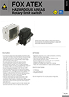
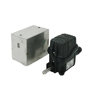
TER FOX ATEX Explosion Proof Rotary Limit Switch
The TER FOX ATEX Explosion Proof Rotary Limit Switch is a specialised electromechanical control device designed to control and measure the movement of industrial machinery operating in potentially explosive environments. Combining the proven operating principles of a geared rotary limit switch with construction specifically developed for hazardous-area applications, FOX ATEX provides machine builders, system integrators and industrial operators with a highly configurable solution for monitoring shaft rotation, controlling machine travel and establishing predetermined stopping or switching positions.
Rotary limit switches are widely used where the movement of a machine can be accurately related to the rotation of a shaft. Rather than detecting only the immediate physical position of a moving component, FOX ATEX uses a mechanical transmission system to convert shaft rotation into controlled movement of internal adjustable cams. These cams operate electrical switches at predetermined points, allowing the device to provide repeatable control signals throughout the movement of the machinery.
This operating principle makes FOX ATEX particularly suitable for industrial machines where movement occurs over multiple shaft revolutions. Through a wide selection of available revolution ratios, the rotary movement of the machine can be mechanically reduced and translated into precise switching positions within the limit switch.
TER offers FOX ATEX with revolution ratios ranging from 1:3 to 1:2870, allowing the device to be adapted to a broad range of machinery and movement requirements. A cam set can accommodate up to four switches, providing multiple switching points within a compact rotary control device.
Explosion Proof Rotary Limit Switch for Industrial Machinery
The defining characteristic of FOX ATEX is its suitability for industrial applications where potentially explosive atmospheres may be present.
Electrical and electromechanical equipment used in hazardous areas requires careful selection because conventional industrial components may not provide the protection required by the surrounding environment. FOX ATEX has been specifically developed by TER as part of its Explosion Proof product range for machinery operating under these more demanding conditions.
The product combines movement control, adjustable mechanical switching and hazardous-area construction in a single rotary limit switch platform.
Designed to Control and Measure Machine Movement
FOX ATEX is designed to control and measure the movement of industrial machinery through the rotation of its input shaft.
As the connected machine shaft rotates, the FOX ATEX transmission system converts this rotation into controlled movement of the internal cam mechanism. When the cams reach their predetermined positions, they operate the associated electrical switches.
The resulting switch signals can then be incorporated into the machine control system to stop movement, change operating sequences, indicate position or perform other control functions.
Rotary Movement Monitoring
Rotary limit switches provide an effective method of monitoring machine travel when linear or angular movement can be related mechanically to shaft rotation.
This is particularly useful for equipment such as hoists, winches, cranes, industrial doors and other machines where the position of a moving component corresponds to the number of revolutions performed by a drum, gearbox, shaft or drive mechanism.
FOX ATEX converts this mechanical rotation into repeatable electrical switching points without requiring a conventional electronic position sensor.
Mechanical Gear Reduction System
At the centre of the FOX ATEX is a geared transmission system designed to transfer movement from the input shaft to the adjustable cams and other movement detection devices.
TER uses a primary input reduction stage consisting of a worm gear and helical toothed gear. Depending on the required revolution ratio, one or more secondary output stages consisting of pairs of straight toothed gears are then incorporated into the transmission.
This arrangement allows substantial mechanical reduction to be achieved within a compact rotary limit switch assembly.
Primary Input Reduction Stage
The primary reduction stage receives the movement of the machine through the FOX ATEX input shaft.
A worm gear and helical toothed gear provide the initial mechanical reduction, translating the incoming shaft rotation into movement suitable for the internal control mechanism.
The use of a geared mechanical system provides a direct relationship between machine rotation and cam position, allowing the switching sequence to be established mechanically.
Secondary Output Reduction Stages
Additional secondary reduction stages can be used to establish the required overall revolution ratio.
TER achieves these secondary stages through combinations of straight toothed gears. By selecting the appropriate gear arrangement, FOX ATEX can accommodate a wide range of machine travel requirements.
This modular approach to mechanical reduction is what enables the product to offer revolution ratios extending from 1:3 through to 1:2870.
Revolution Ratios from 1:3 to 1:2870
The broad range of available revolution ratios is one of the most important characteristics of the TER FOX ATEX.
Ratios from 1:3 to 1:2870 allow the rotary limit switch to be matched to machinery with significantly different movement ranges. A machine requiring switching over relatively few input-shaft revolutions can use a lower reduction ratio, while applications involving many revolutions can use a much higher ratio.
Selecting the correct ratio allows the available cam movement to correspond appropriately with the required machine travel.
Matching the Revolution Ratio to the Machine
Correct revolution ratio selection is fundamental to the successful application of a rotary limit switch.
The engineer should first determine how many revolutions of the machine or drive shaft correspond to the complete movement that must be monitored. The FOX ATEX ratio can then be selected so that the internal cam mechanism operates across an appropriate portion of its available movement.
Using a suitable ratio provides better adjustment capability and allows the required switching positions to be established accurately.
Adjustable Cam Switching System
FOX ATEX uses adjustable cams to establish the required switching points.
Each cam is mechanically positioned so that it operates its corresponding switch at a predetermined point in the rotation of the machine.
TER provides accurate cam adjustment by means of adjustment screws, allowing the switching position to be fine-tuned during commissioning.
This mechanical adjustment system provides flexibility when matching the limit switch to the actual operating travel of the machinery.
Precise Cam Adjustment
Accurate switching positions are particularly important in lifting, material-handling and automated machinery.
Small changes in the cam position alter the point at which the associated electrical switch changes state. Adjustment screws allow technicians to refine these positions after the FOX ATEX has been mechanically installed.
This can be valuable during commissioning because the actual stopping position of machinery can be affected by factors such as mechanical inertia, braking performance and the characteristics of the drive system.
Up to Four Switches
The FOX ATEX can be equipped with a cam set incorporating up to four switches.
Multiple switches allow several independent switching positions or functions to be established from the same input-shaft movement.
For example, different switches may be used for operational travel limits, preliminary control points or additional machine-control functions depending on the electrical and safety architecture of the equipment.
The exact function assigned to each switch is determined by the machine designer and the selected FOX ATEX configuration.
Two, Three or Four Switch Configurations
The FOX ATEX platform can be configured with two, three or four switches according to the application requirements.
A simpler machine may require only two switching points, while more sophisticated equipment can use additional switches to provide extra stages of movement control.
This configurability allows machine builders to select the number of contacts required without unnecessarily increasing the complexity of the control system.
Snap Action Switches
FOX ATEX can be configured with snap action switches featuring 1NO+1NC contacts.
A snap action mechanism changes the electrical contact state rapidly once the mechanical operating point is reached. This provides a clearly defined switching action as the cam operates the switch.
The combination of one normally open and one normally closed contact provides flexibility when integrating the limit switch into machine control circuits.
1NO+1NC Contact Configuration
The 1NO+1NC arrangement provides one normally open and one normally closed contact within the switch.
This allows the control system to use either contact state or, where appropriate, incorporate both contacts into the machine circuit.
Such flexibility can be valuable for applications requiring separate control logic, indication or monitoring functions from a single mechanical switching point.
Slow Action Switches
TER also offers FOX ATEX configurations using slow action switches with 1NC contacts.
Unlike a snap action mechanism, a slow action switch changes contact state according to the mechanical movement applied by the cam.
The selection between snap and slow action should be based on the required control function, electrical circuit and safety requirements of the machinery.
Positive Opening NC Contacts
FOX ATEX provides positive opening normally closed contacts for applicable safety functions.
Positive opening is an important characteristic in machine safety circuits because opening of the NC contact is achieved through direct mechanical action rather than relying solely on spring force.
This can make the contact arrangement suitable for safety-related limit functions when incorporated correctly into an appropriately designed machine safety system.
Safety-Related Limit Functions
Rotary limit switches are frequently used to establish limits beyond which machinery should not normally travel.
In lifting equipment, for example, a rotary limit switch can be mechanically linked to the hoisting mechanism so that predetermined switch positions correspond to defined travel limits.
Positive-opening NC contacts provide a useful characteristic for safety-related functions, although the overall safety performance depends on the architecture and validation of the complete machine control system.
Mechanical Life up to 10 Million Operations
The switches used within FOX ATEX provide mechanical life of up to 10 million operations.
High mechanical endurance is particularly valuable in industrial equipment where the limit switch may operate repeatedly throughout the service life of the machine.
The actual operating life achieved in an installation will depend on application conditions, switching frequency, electrical loading, mechanical adjustment, environmental exposure and maintenance.
AC-15 Industrial Control Applications
The FOX ATEX switch specifications include an AC-15 utilisation category.
AC-15 is associated with the control of electromagnetic loads in AC control circuits and is commonly relevant to industrial control devices such as contactors, relays and similar equipment.
This makes FOX ATEX well suited to integration into conventional industrial machine-control architectures.
3 A at 250 Vac Rated Operational Performance
TER specifies a rated operational current of 3 A at a rated operational voltage of 250 Vac for the FOX ATEX switches under the stated AC-15 utilisation category.
These ratings should be considered when designing the electrical interface between the limit switch and the machine control circuit.
Where larger loads are involved, the FOX ATEX should normally operate an appropriate control interface rather than switching loads outside the specified contact capability.
10 A Rated Thermal Current
The FOX ATEX switch specifications include a rated thermal current of 10 A.
This value forms part of the electrical characteristics of the switching elements and should be considered together with the rated operational current, utilisation category and operational voltage.
Correct electrical selection helps ensure dependable switching performance and appropriate service life.
300 Vac Rated Insulation Voltage
TER specifies a rated insulation voltage of 300 Vac for the FOX ATEX switches.
The insulation rating forms part of the overall electrical specification and should be considered when incorporating the device into the control system.
Machine designers should ensure that the electrical characteristics of the complete circuit remain compatible with the ratings of the selected FOX ATEX configuration.
Screw-Type Electrical Terminals
Electrical connections to the FOX ATEX switches are made using screw-type terminals.
Screw terminals provide a familiar and serviceable connection method for industrial control wiring.
Conductors should be correctly prepared and secured according to the applicable TER installation instructions to provide a reliable connection and avoid loose conductors within the enclosure.
Industrial Rotation Speed Capability
The maximum permitted input rotation speed of FOX ATEX depends on the selected revolution ratio.
For revolution ratios equal to or greater than 1:16, TER specifies a maximum rotation speed of 800 rpm. For ratios below 1:16, the maximum is 200 rpm.
Specific 1:50 and 1:100 configurations can accommodate rotation speeds up to 1500 rpm.
This makes correct ratio selection important not only for the required machine travel but also for the operating speed of the connected shaft.
Up to 1500 rpm for Selected Ratios
The ability of selected 1:50 and 1:100 configurations to operate at up to 1500 rpm extends FOX ATEX into applications involving relatively high input-shaft speeds.
The actual rotational speed of the machine interface should be established before selecting the limit switch configuration.
A FOX ATEX should not be selected solely according to the desired revolution ratio without also confirming that the input speed remains within the permitted value for that ratio.
Stainless Steel Transmission Shafts
FOX ATEX incorporates transmission and gear-driving shafts manufactured from stainless steel, with TER identifying AISI 430F or AISI 303 materials within the product construction.
Stainless steel provides good mechanical durability and contributes to the robust construction required for demanding industrial applications.
The transmission shaft forms a critical part of the mechanical path between the machine input and the internal gear and cam system.
Ball Bearing Supported Worm Gear Shaft
The worm gear transmission shaft rotates on ball bearings, supporting smooth mechanical operation of the primary reduction stage.
Reliable bearing support is important because the transmission system repeatedly converts input rotation into controlled cam movement throughout the operating life of the machine.
This construction contributes to consistent operation of the internal gearing and switching mechanism.
Self-Lubricating Technopolymer Gears
TER uses self-lubricating technopolymer gears and driving bushes within the FOX ATEX transmission system.
These materials provide wear resistance while supporting reliable mechanical movement throughout repeated operating cycles.
The use of self-lubricating components also helps create a transmission system suited to long-term industrial service without relying on frequent lubrication of the internal gearing.
Technopolymer Base and Cover
The FOX ATEX construction incorporates a technopolymer base and cover, with TER identifying a polyamide 66 housing and EPM gasket in the current product documentation.
The housing materials are selected to provide mechanical durability and environmental protection while maintaining the compact dimensions required for installation on industrial machinery.
All materials and components are selected for wear resistance and protection of the internal mechanism against environmental contamination.
Polyamide 66 Housing
Polyamide 66 provides a robust engineering material for the FOX ATEX enclosure.
Its use allows TER to produce a durable housing capable of protecting the internal gearing, cams and electrical switching components from demanding industrial conditions.
The enclosure works together with the sealing system to establish the specified ingress-protection performance.
EPM Gasket Sealing
FOX ATEX incorporates an EPM gasket as part of its environmental sealing arrangement.
The gasket helps prevent the ingress of dust and water into the internal mechanical and electrical components when the unit is correctly assembled and installed.
Maintaining the integrity of this sealing system is important during installation and servicing.
IP65 and Enhanced IP69 Protection
Current TER documentation identifies FOX ATEX with IP65/IP69 protection, with the stainless-steel cage version providing IP65/IP69K protection.
These ingress-protection characteristics make the product particularly suitable for demanding industrial installations where dust, moisture and environmental contamination can affect control equipment.
The exact protection rating applicable to the selected FOX ATEX version should be confirmed from its current technical documentation and product marking.
Stainless Steel Protective Cage
FOX ATEX is available in a version equipped with a stainless-steel protective cage.
The cage provides additional mechanical protection to the enclosure and forms an important part of the hazardous-area construction of this version.
TER also offers a version without the cage where the required external protection is the responsibility of the customer, making correct selection and installation particularly important.
Compact Industrial Dimensions
Despite its wide range of revolution ratios and ability to accommodate up to four switches, FOX ATEX maintains compact overall dimensions.
TER documentation lists dimensions of approximately 123 x 114 x 83 mm for the version with the protective cage and approximately 117 x 102 x 75 mm for the version without the cage.
This compact construction can assist machine designers where installation space around the drive, drum or rotating mechanism is limited.
Flexible Cable Entry Arrangements
FOX ATEX can be configured with dedicated cable glands or connectors according to the installation requirements.
TER documentation identifies cable-entry arrangements including M20 and combinations such as M20+M16 or M20+M20 depending on configuration.
Correct cable-entry selection is particularly important in hazardous-area applications because the integrity of the complete enclosure and installation must be maintained.
ATEX-Compliant Cable Glands and Connectors
TER offers dedicated cable glands and connectors for FOX ATEX applications.
Using appropriate components at the cable entry helps maintain the intended environmental and hazardous-area characteristics of the installation.
Cable glands and connectors should be selected according to the cable type, dimensions, installation conditions and applicable hazardous-area requirements.
Flanges, Pinion Gears and Couplings
FOX ATEX is available with a selection of mechanical accessories including flanges, pinion gears and couplings.
These options make it easier to interface the rotary limit switch with different machine drive arrangements.
Depending on the equipment design, the limit switch may be connected directly to a shaft, gearbox or other rotating component through an appropriate mechanical interface.
Universal Adapter Plates
TER also offers plates with universal adapters for replacing existing systems.
This can be particularly useful when upgrading older machinery or replacing an existing rotary limit switch where the original mounting arrangement differs from the FOX ATEX footprint.
Adapter solutions can reduce the amount of mechanical modification required during retrofit projects while allowing the machinery to benefit from a current TER rotary limit switch solution.
Retrofit Applications
The availability of universal adapter plates makes FOX ATEX relevant not only to new machinery but also to industrial retrofit and modernisation projects.
Older cranes, hoists, doors and process equipment may contain rotary limit switches that are obsolete, difficult to source or no longer appropriate for the required application.
A correctly engineered FOX ATEX retrofit can provide a modern replacement while minimising changes to the surrounding machine structure.
ATEX Certification
FOX ATEX carries CE marking and ATEX certification for the applicable hazardous-area configurations.
ATEX Directive 2014/34/EU establishes requirements for equipment intended for use in potentially explosive atmospheres.
Selection of FOX ATEX should therefore consider the complete equipment marking, zone classification and installation requirements rather than relying on the general term explosion proof alone.
Category II 3D and Zone 22 Applications
Current TER documentation identifies FOX ATEX for Category II 3D applications associated with Zone 22 potentially explosive dust environments.
The version with the stainless-steel protective cage incorporates the required protection as part of the product arrangement, while TER identifies additional customer responsibility for protection when the version without the cage is used.
The exact marking on the selected device and its current certificate should always be checked against the hazardous-area classification of the installation.
Explosion Protection Requires Correct Installation
ATEX suitability depends on more than the selection of an individual certified component.
The mounting arrangement, cable entries, wiring, surrounding mechanical protection and maintenance practices all contribute to the integrity of the final installation.
For this reason, FOX ATEX should be installed and serviced by personnel familiar with electrical equipment used in potentially explosive environments and in accordance with the current TER instructions.
Industrial Applications for FOX ATEX
TER identifies FOX ATEX for a broad range of industrial machinery where movement must be controlled or measured in potentially explosive environments.
Applications include winches and hoists, overhead travelling cranes, gantry cranes, harbour cranes, industrial high-speed doors, gates and barriers, silos and oil and gas equipment.
The wide range of available revolution ratios and configurable cam switches allows the same product family to be adapted to substantially different machine movements.
Winches and Hoists
Winches and hoists are particularly well suited to rotary limit switch control because drum or gearbox rotation can be directly related to the movement of the load or lifting mechanism.
FOX ATEX can monitor this rotation and operate switches at predetermined positions, providing control information to the hoisting system.
For equipment operating in suitable hazardous areas, the ATEX configuration adds the specialised protection required for the surrounding environment.
Overhead Travelling and Gantry Cranes
Overhead travelling cranes and gantry cranes can use rotary limit switches for movement control across lifting and travel mechanisms.
FOX ATEX provides a mechanically driven solution with adjustable switching points and multiple switch configurations, making it suitable for complex crane control applications.
The available positive-opening NC contacts also provide an important characteristic for appropriately engineered safety-related limit functions.
Harbour Crane Applications
Harbour cranes operate in demanding industrial environments where reliable movement control is essential.
The combination of robust construction, adjustable cam switching, broad revolution ratios and enhanced ingress protection makes FOX ATEX suitable for specialised crane applications where the hazardous-area classification also matches the product configuration.
Industrial Doors, Gates and Barriers
TER also identifies industrial high-speed doors, gates and barriers among the applications for FOX ATEX.
The rotation of a drive shaft can be used to establish the position of the moving door or barrier, allowing the adjustable cams to generate switching signals at the required opening and closing limits.
Multiple switches can also provide additional intermediate or protective control points where required by the machine design.
Silo Applications
FOX ATEX is suitable for appropriately classified silo applications where rotary machinery requires position or movement control.
The Category II 3D configuration is particularly relevant to suitable Zone 22 dust environments, subject to confirmation of the actual hazardous-area classification and complete product marking.
The sealed construction also helps protect the internal mechanism against the dust commonly encountered in bulk-material handling installations.
Oil and Gas Applications
TER identifies oil and gas equipment among the applications for FOX ATEX.
Machinery within these environments can require robust movement-control components capable of operating under demanding industrial conditions while satisfying the applicable hazardous-area requirements.
Correct product selection must be based on the actual classified area, hazardous substance, equipment marking and environmental conditions of the installation.
A Highly Configurable Explosion Proof Movement Control Solution
The TER FOX ATEX combines a broad 1:3 to 1:2870 revolution ratio range, up to four adjustable cam-operated switches and a robust geared transmission system within a compact hazardous-area rotary limit switch.
Snap action 1NO+1NC and slow action 1NC switching options, positive-opening NC contacts, mechanical life up to 10 million operations and AC-15 electrical performance provide the foundation for dependable industrial machine control.
Stainless-steel shafts, self-lubricating technopolymer gearing, a polyamide 66 enclosure, environmental sealing and the optional stainless-steel protective cage further support operation in demanding machinery environments.
For winches, hoists, cranes, industrial doors, silos, oil and gas equipment and other machines requiring mechanically derived position control in appropriately classified potentially explosive environments, the TER FOX ATEX provides a versatile and configurable rotary limit switch solution.
Detailed Gear Ratio Engineering of the TER FOX ATEX
The TER FOX ATEX uses a mechanical reduction system to translate rotation of the connected machine shaft into controlled movement of the internal cam assembly. This geared relationship is central to the operation of the rotary limit switch because it determines how many input-shaft revolutions correspond to one complete movement of the cam mechanism.
TER offers a wide range of revolution ratios from 1:3 to 1:2870, allowing the FOX ATEX to be adapted to machinery with very different travel lengths, drum diameters, gearbox arrangements and mechanical operating cycles.
Correct ratio selection is one of the most important steps when specifying the FOX ATEX because the chosen gearing affects both the usable movement range of the cams and the maximum permitted input-shaft speed.
Understanding the 1:3 to 1:2870 Ratio Range
The revolution ratio expresses the relationship between the number of revolutions at the input shaft and the corresponding movement of the internal switching mechanism.
Lower ratios are suited to machinery where the required switching points occur over relatively few shaft revolutions, while higher ratios are appropriate where the machine performs many revolutions across its complete travel.
The broad 1:3 to 1:2870 range enables the same FOX ATEX product family to be used across a wide variety of cranes, hoists, winches, doors, gates, barriers and industrial process machinery.
Low Reduction Ratios
Lower reduction ratios are useful where the machine shaft completes a relatively small number of revolutions across the operating range.
In these applications, excessive reduction would compress the useful cam movement into too small a portion of the available adjustment range.
Selecting an appropriately low ratio allows the available cam rotation to be used effectively and gives technicians better control over the final switching positions.
High Reduction Ratios
Higher reduction ratios are required where the monitored machine shaft performs many revolutions before the desired switching position is reached.
This is common in hoisting drums, winches and other lifting mechanisms where a large amount of rope travel may correspond to a substantial number of shaft revolutions.
A high reduction ratio allows these many input revolutions to be translated into a manageable amount of cam movement within the FOX ATEX.
Calculating the Required Ratio
Before selecting the FOX ATEX revolution ratio, the engineer should determine how many revolutions of the monitored shaft occur between the two extreme positions that need to be controlled.
Factors such as drum diameter, gearbox reduction, rope layering, lead screw pitch or other mechanical relationships can affect the total number of input revolutions.
Once the full machine travel has been converted into shaft revolutions, a suitable FOX ATEX ratio can be selected to provide adequate cam movement and adjustment range.
Importance of Mechanical Travel Calculations
Accurate travel calculations improve both commissioning and long-term reliability.
If the selected ratio is too low, the cam mechanism may rotate too far before the machine reaches the end of its travel. If the ratio is too high, the cam movement may be too small to provide convenient and accurate adjustment.
Correct mechanical calculations therefore help ensure that the FOX ATEX uses an appropriate proportion of its available cam range.
Input Rotation Speed Limits
The maximum input rotation speed of FOX ATEX depends on the selected revolution ratio.
TER specifies a maximum input speed of 200 rpm for ratios below 1:16 and 800 rpm for ratios equal to or greater than 1:16.
Selected 1:50 and 1:100 configurations are capable of operating at input speeds up to 1500 rpm.
These limits must be considered alongside the required revolution ratio when configuring the device.
200 rpm for Ratios Below 1:16
For configurations using revolution ratios below 1:16, the specified maximum input speed is 200 rpm.
This lower speed limit reflects the characteristics of the gearing used in the lower-ratio transmission arrangements.
Where the monitored shaft operates faster than this, the engineer should evaluate whether a different FOX ATEX ratio, an additional mechanical reduction stage or another drive arrangement is required.
800 rpm for Ratios of 1:16 and Above
For revolution ratios equal to or greater than 1:16, TER specifies a maximum input speed of 800 rpm.
This higher permitted speed expands the range of machinery that can be connected directly to the FOX ATEX.
Nevertheless, actual machine speed should be determined under all operating conditions, including potential overspeed situations, before confirming the final configuration.
Up to 1500 rpm on Selected 1:50 and 1:100 Versions
Specific FOX ATEX configurations using 1:50 and 1:100 revolution ratios can operate at input speeds up to 1500 rpm.
This provides a valuable option for machinery where the monitored shaft rotates relatively quickly but a substantial mechanical reduction is still required.
The exact product configuration should be checked against current TER technical data before applying the higher 1500 rpm limit.
Relationship Between Speed and Ratio Selection
Revolution ratio and shaft speed should always be evaluated together.
A ratio that appears mechanically suitable for the machine travel may not be appropriate if the connected shaft exceeds the permitted input speed for that gearing arrangement.
For this reason, a complete FOX ATEX selection should include both the number of shaft revolutions across the machine travel and the maximum rotational speed of the input shaft.
Cam Set Configuration
The internal cam set is the mechanism that determines where the FOX ATEX electrical switches operate.
Each cam is positioned relative to the input shaft so that its associated switch changes state at a predetermined point in the machine movement.
The adjustable cam system allows the machine designer or commissioning technician to establish precise switching positions according to the actual travel requirements.
Up to Four Independent Switching Functions
The FOX ATEX can accommodate up to four switches, allowing several independent switching functions to be derived from the same mechanical input.
This can be valuable in applications where the control system requires more than a simple upper and lower limit.
Additional switches can be used for intermediate positions, preliminary stop commands, auxiliary functions or separate safety-related limits depending on the design of the machine.
Two-Switch Configurations
A two-switch FOX ATEX configuration provides a straightforward arrangement for machinery requiring two primary switching points.
Typical examples can include upper and lower travel limits or open and closed positions.
This configuration can provide a compact and efficient solution where additional intermediate switching functions are not required.
Three-Switch Configurations
Three-switch configurations add an additional control point to the rotary limit switch.
This can be useful where an extra pre-limit, slowdown command or status function is required in addition to the principal travel limits.
The precise function assigned to the third switch depends on the machine control architecture.
Four-Switch Configurations
A four-switch FOX ATEX provides the greatest flexibility within the standard cam set.
Multiple switches can be arranged to provide staged control functions, duplicated limits or additional operating positions.
This can be especially useful in cranes and hoisting systems where separate operational and protective switching points may be required.
Adjusting Cam Switching Positions
Each FOX ATEX cam can be adjusted using dedicated adjustment screws.
These screws allow technicians to alter the angular position of the cam relative to the transmission mechanism and therefore change the point at which the associated electrical switch operates.
Fine cam adjustment is particularly valuable during machine commissioning, when the theoretical switching position may require refinement to account for real operating conditions.
Allowing for Machine Inertia
Heavy machinery does not necessarily stop at the exact instant a limit switch operates.
Motors, drums, loads and mechanical transmission systems can continue to move due to inertia after the switch signal is generated.
The final cam positions should therefore be adjusted with consideration for actual stopping distance, braking performance and the dynamic behaviour of the machine.
Pre-Limit and Final Limit Functions
Multiple cam switches can be used to create staged movement control.
A first switch may initiate slowing or controlled deceleration before a second switch establishes the final travel limit.
This type of architecture can reduce mechanical shock and improve control of heavy moving systems when designed correctly.
Operational and Safety Limits
Where the machine control system requires separate operational and protective limits, different FOX ATEX switches can be assigned to those functions.
An operational limit can be used for normal automatic stopping, while an additional switch may provide a separate protective input.
The overall safety performance depends on the complete control system and should be engineered and validated according to the applicable machinery safety requirements.
Snap Action Switch Configuration
FOX ATEX can be fitted with snap action switches using 1NO+1NC contacts.
Snap action switching provides a rapid change of electrical state once the cam reaches the operating point.
This creates a well-defined switching transition and can be suitable for conventional industrial control functions requiring both normally open and normally closed contacts.
Benefits of 1NO+1NC Contacts
The 1NO+1NC configuration gives the machine designer two complementary contact states from the same switching element.
The normally closed contact can be used for one control function while the normally open contact can provide another function, status indication or control input.
The exact wiring arrangement should be selected according to the machine electrical schematic and the required control logic.
Slow Action Switch Configuration
TER also offers slow action switches with 1NC contacts.
In a slow action mechanism, contact movement follows the mechanical displacement applied by the cam rather than using the rapid snap mechanism of a snap action switch.
This provides an alternative switching characteristic for applications where direct mechanical contact movement is preferred.
Positive Opening Contact Operation
Positive opening is an important characteristic of the normally closed contacts available in FOX ATEX configurations intended for safety functions.
The contact is mechanically forced open through direct movement of the actuator mechanism.
This is valuable in safety-related applications because separation of the contacts does not rely solely on a return spring.
Using Positive Opening Contacts in Machine Safety
Positive opening contacts can form part of a safety-related machine control circuit where mechanically enforced contact separation is required.
However, the presence of a positive-opening switch does not by itself establish a complete safety function.
Redundancy, diagnostics, control architecture, fault response and validation must also be considered according to the required safety performance.
Electrical Utilisation Category AC-15
FOX ATEX switches are specified for AC-15 control applications.
AC-15 is commonly associated with switching electromagnetic loads used in industrial control systems, including relay and contactor coils.
This rating helps define the practical switching capability of the contacts under typical machine-control conditions.
Rated Operational Current 3 A
TER specifies rated operational current of 3 A at 250 Vac under the stated AC-15 utilisation category.
This rating should be respected when designing the control circuit.
Where the machine load exceeds the permitted switch capability, an appropriate relay, contactor or other interface should be used rather than applying excessive load directly to the FOX ATEX contact.
Rated Thermal Current 10 A
The rated thermal current of 10 A forms another part of the FOX ATEX switch specification.
This rating describes the current the device can carry continuously under the specified thermal conditions rather than the switching capability under a particular utilisation category.
It should therefore be considered separately from the AC-15 operational rating.
Rated Insulation Voltage 300 Vac
FOX ATEX switches have a rated insulation voltage of 300 Vac.
This characteristic should be considered when integrating the device into the electrical architecture of the machine.
Control circuit voltage, insulation coordination and installation conditions should all remain compatible with the switch ratings.
Mechanical Endurance
The switches can provide mechanical life of up to 10 million operations.
This high endurance supports applications involving frequent repetitive movement such as lifting systems, automatic doors and industrial material-handling machinery.
Actual service life will depend on the operating environment, switch loading, cam adjustment and maintenance condition of the machine.
Screw Terminal Connections
FOX ATEX uses screw-type terminals for the electrical connections.
This provides a familiar industrial wiring method and allows individual conductors to be connected directly to the required switch contacts.
Correct conductor preparation and tightening are important because loose terminals can cause unreliable switching, heating or intermittent machine faults.
Hazardous Dust Area Applications
Current TER documentation identifies FOX ATEX within Category II 3D configurations intended for suitable potentially explosive dust environments.
This is particularly relevant to Zone 22 applications, where combustible dust may be present occasionally under abnormal operating conditions.
The precise suitability of the device must always be confirmed from the current product marking and certificate for the specific installation.
Zone 22 Equipment Selection
Zone 22 equipment selection should be based on the actual hazardous-area classification established for the site.
The type of combustible dust, environmental temperature, required protection level and installation conditions should all be considered.
The FOX ATEX marking should then be compared directly with these requirements before the product is installed.
Protective Cage Version
TER offers FOX ATEX with a stainless-steel protective cage.
The cage increases mechanical protection around the limit switch and forms an important part of the explosion-protection arrangement of this version.
This configuration is especially useful where external mechanical impact or additional enclosure protection must be considered.
Version Without Protective Cage
A FOX ATEX version without the stainless-steel cage is also available.
In this configuration, TER documentation places additional responsibility on the customer to provide the required external mechanical protection.
The surrounding machine structure and installation method must therefore be engineered accordingly.
IP65/IP69 Protection
Current TER technical documentation identifies FOX ATEX with IP65/IP69 protection.
This provides a high level of resistance to dust and water ingress when the unit is correctly installed and maintained.
Such protection is particularly valuable for cranes, material-handling systems, silos and industrial machinery exposed to demanding environmental conditions.
IP65/IP69K with Stainless-Steel Cage
The version equipped with the stainless-steel protective cage is identified with IP65/IP69K protection in current TER documentation.
This enhanced rating supports use in environments where strong water ingress resistance and robust external protection are required.
The complete installation must still preserve the required sealing at cable entries and enclosure joints.
Operating Temperature Considerations
FOX ATEX is designed for operation across a broad industrial temperature range.
Current TER product data identifies an extreme-temperature capability extending up to -25°C to +75°C, depending on the configuration and applicable documentation.
Because hazardous-area equipment may have certification conditions tied to ambient temperature, the exact rating applicable to the selected version should be verified before installation.
Technopolymer Gear Advantages
The self-lubricating technopolymer gears used inside FOX ATEX provide several practical advantages.
They support repeated mechanical operation while reducing the need for routine internal lubrication.
The material selection also contributes to wear resistance and smooth operation of the reduction mechanism.
Stainless-Steel Shaft Construction
Stainless-steel shafts are used within the FOX ATEX transmission system to provide mechanical durability and resistance to industrial service conditions.
These shafts form a critical link between the external machine rotation and the internal gearing.
Reliable shaft construction is essential for maintaining the mechanical relationship between the monitored machinery and the cam switching positions.
Ball Bearing Support
The worm gear shaft is supported by ball bearings.
This helps reduce friction and supports consistent rotation of the primary reduction stage throughout repeated operating cycles.
Stable bearing support contributes to repeatable cam positioning and dependable switch operation.
Cable Entry Configuration
FOX ATEX can be supplied with different cable-entry arrangements depending on the required configuration.
TER documentation identifies options including M20, M20+M16 and M20+M20 combinations.
The correct arrangement should be selected according to the number and dimensions of cables, internal wiring requirements and hazardous-area installation method.
ATEX-Compatible Cable Glands
Cable glands used with FOX ATEX must be appropriate for the hazardous-area application.
TER offers dedicated glands and connectors intended for the product range.
Correct gland selection helps maintain both enclosure sealing and the certified characteristics of the installation.
Cable Diameter and Gland Selection
The external cable diameter should be matched correctly to the selected gland.
A gland that is too large or too small for the cable can compromise sealing and mechanical retention.
This becomes especially important in hazardous-area installations where the cable entry is part of the complete protective system.
Mechanical Coupling to the Machine
The FOX ATEX must be mechanically connected to a rotating component whose movement accurately represents the machine travel being monitored.
Depending on the application, this connection may be made through a shaft, coupling, pinion or other mechanical interface.
The coupling arrangement should minimise backlash and avoid excessive radial or axial load on the limit switch shaft.
Pinion Gear Options
TER offers pinion gear accessories for applications where the FOX ATEX must engage with an existing gear or rotating mechanical system.
This can simplify integration when direct shaft coupling is not practical.
The gear ratio introduced by the external pinion arrangement must be included when calculating the overall relationship between machine movement and FOX ATEX cam position.
Flange Mounting Options
Flanges are available to support different mechanical mounting arrangements.
The mounting interface should hold the FOX ATEX rigidly and maintain correct alignment with the drive connection.
Poor alignment can introduce unwanted mechanical loads and affect long-term reliability.
Coupling Accessories
Mechanical couplings can help connect the FOX ATEX input shaft to the machine drive system while accommodating the required installation geometry.
The selected coupling should be suitable for the speed, torque and alignment conditions of the application.
Excessive misalignment should not be compensated for solely by the coupling.
Universal Adapter Plates for Retrofit Projects
TER offers universal adapter plates that can assist in replacing existing rotary limit switches.
This is particularly useful on older cranes, hoists and process machinery where the original mounting pattern differs from the FOX ATEX.
Using an adapter plate can reduce the amount of machine modification required during a retrofit.
Replacing Obsolete Rotary Limit Switches
Industrial machinery often remains in service much longer than the original control components installed on it.
When an older rotary limit switch becomes obsolete, a FOX ATEX retrofit can provide a modern replacement platform with current configuration options and hazardous-area capability.
The replacement should be engineered carefully so that the mechanical ratio, switch sequence and electrical functions replicate or improve the original control strategy.
Commissioning the FOX ATEX
Commissioning should begin by confirming that the mechanical ratio and shaft connection correspond correctly with the machine travel.
The cam switching points can then be adjusted progressively while the machine is operated under controlled conditions.
Final limits should be verified at appropriate operating speed and load conditions rather than relying solely on static adjustment.
Verifying Switch Operation
Each configured switch should be tested individually during commissioning.
The technician should confirm the mechanical operating position, electrical contact change and corresponding response of the machine control system.
This helps identify wiring errors, incorrectly adjusted cams or control-logic issues before the equipment enters normal service.
Checking Direction of Rotation
The direction of the FOX ATEX input shaft should be confirmed against the intended cam sequence.
If the mechanical drive direction is reversed, the cam operating sequence can differ from the expected machine movement.
Direction should therefore be established before final cam adjustment.
Allowing for Backlash
Mechanical backlash within the machine drive system can affect the relationship between shaft position and cam operation.
This should be considered particularly where the machine frequently reverses direction.
Where accurate limit repeatability is required, backlash should be minimised within the complete mechanical transmission.
Final Engineering Checks
Before placing a FOX ATEX installation into service, the engineer should confirm the selected revolution ratio, maximum input speed, cam positions, switch contact arrangement and electrical ratings.
The hazardous-area configuration, cable glands, protective cage requirements and enclosure sealing should also be verified.
Mechanical mounting, shaft alignment and the machine response to each switch should be checked as part of final commissioning.
A Flexible Rotary Limit Switch Platform
The TER FOX ATEX provides a broad combination of mechanical and electrical configuration options within one compact explosion-protected rotary limit switch family.
Revolution ratios from 1:3 to 1:2870, input speeds from 200 rpm up to 1500 rpm on selected configurations and up to four adjustable switches allow the device to be matched closely to the movement characteristics of industrial machinery.
Snap action 1NO+1NC and slow action 1NC switching options, positive-opening contacts, AC-15 electrical performance and mechanical life up to 10 million operations provide a robust foundation for industrial machine control.
Combined with IP65/IP69 or IP65/IP69K protection, stainless-steel protective cage options, ATEX-compatible cable entries and a range of mounting and coupling accessories, FOX ATEX provides machine builders and system integrators with a highly adaptable solution for movement control in suitably classified potentially explosive environments.
Industrial Applications for the TER FOX ATEX
The TER FOX ATEX Explosion Proof Rotary Limit Switch is designed for industrial machinery where movement must be controlled or measured through shaft rotation in potentially explosive environments.
Its broad revolution-ratio range, configurable cam set, robust mechanical transmission and hazardous-area construction make it particularly suitable for lifting equipment, material-handling machinery, access systems, bulk storage equipment and specialised industrial installations.
TER identifies applications including winches and hoists, overhead travelling cranes, gantry cranes, harbour cranes, industrial high-speed doors, gates and barriers, silos and oil and gas equipment.
Winch Applications
Winches are one of the most natural applications for a rotary limit switch because the rotation of the winch drum can be directly related to cable or rope travel.
By mechanically coupling FOX ATEX to the winch drive system, the internal gearing and cams can be configured so that electrical switching occurs at predetermined points during drum rotation.
This allows the machine control system to establish limits, staged operating positions or additional switching functions without relying on a separate linear position device.
Hoist Applications
Hoisting systems often require dependable control of upper and lower travel limits.
The movement of the load can be related to rotation of the hoist drum, gearbox or another rotating element, allowing FOX ATEX to monitor the travel mechanically.
Multiple cam switches can be used to provide separate operating and protective limits depending on the control architecture of the hoist.
Upper and Lower Hoist Limits
A common hoist application is the establishment of upper and lower travel limits.
One cam can be adjusted to operate at the upper travel position while another can be set for the lower position.
Additional switches can be incorporated for slowdown, pre-limit or auxiliary functions where the machine requires more than two switching points.
Pre-Limit Functions in Hoisting Systems
In heavy lifting equipment, stopping motion gradually can help reduce shock loading and improve machine control.
A pre-limit switch can be adjusted to operate before the final end-of-travel switch, allowing the control system to initiate deceleration before the machine reaches the final limit.
The final switch can then act at a separate position according to the required control and safety strategy.
Overhead Travelling Crane Applications
Overhead travelling cranes can use rotary limit switches on lifting, travel or other rotating mechanisms.
The FOX ATEX can be mechanically linked to the relevant drive so that machine movement is translated into repeatable cam switching positions.
Where the crane operates in an appropriately classified hazardous area, the ATEX design makes FOX ATEX suitable for applications where a conventional rotary limit switch would not be appropriate.
Gantry Crane Applications
Gantry cranes often operate in demanding outdoor or industrial environments and may require robust movement-control components capable of withstanding dust, moisture and repeated operation.
The FOX ATEX combines enhanced ingress protection, stainless-steel mechanical components and a durable geared transmission with hazardous-area capability.
This makes it suitable for specialised gantry crane applications where both movement control and explosion-protection requirements must be addressed.
Harbour Crane Applications
Harbour cranes can expose electrical control components to particularly demanding conditions, including weather, contamination, vibration and repeated mechanical cycles.
The IP65/IP69 or IP65/IP69K protection available within the FOX ATEX range can provide valuable environmental resistance in these environments.
The product’s configurable gearing and multiple switch options also allow the limit switch to be matched closely to the movement characteristics of the crane mechanism.
Industrial High-Speed Door Applications
TER identifies industrial high-speed doors among the applications for FOX ATEX.
The rotation of the door drive shaft can be used to represent the opening and closing position of the door.
The FOX ATEX cams can then be adjusted to operate at the required fully open, fully closed or intermediate positions.
Gates and Barrier Applications
Industrial gates and barriers can also use rotary movement as the basis for position control.
FOX ATEX can provide repeatable electrical switching at predetermined shaft positions, allowing the control system to recognise open, closed or other defined operating positions.
Where the equipment is installed in a suitably classified potentially explosive environment, the FOX ATEX provides a dedicated hazardous-area solution.
Silo Applications
Silos and bulk-material systems can require rotary limit switches for equipment such as loading mechanisms, discharge systems, gates, conveyors and related machinery.
Where combustible dust can be present, equipment selection must account for the hazardous-area classification.
The FOX ATEX Category II 3D configuration is relevant to suitable Zone 22 dust environments, subject to verification of the actual site requirements and product marking.
Bulk Material Handling Equipment
Bulk material systems can create difficult operating conditions for control equipment because dust, vibration and mechanical wear are common.
The FOX ATEX enclosure, sealing, stainless-steel shaft components and self-lubricating gearing are designed to support operation in demanding industrial environments.
Correct installation and maintenance remain essential to preserving the intended environmental and hazardous-area performance.
Oil and Gas Equipment
TER also identifies oil and gas applications for FOX ATEX.
Industrial equipment within these environments may require movement or position control while operating under stringent hazardous-area requirements.
The exact FOX ATEX configuration should always be selected according to the classified zone, hazardous substance, temperature requirements and complete equipment marking applicable to the installation.
Hazardous-Area Product Selection
Selection of FOX ATEX should begin with the hazardous-area assessment rather than with the mechanical specification alone.
The zone classification, dust characteristics, temperature requirements, equipment category and required protection level should be confirmed first.
The selected FOX ATEX version and any protective cage requirements can then be matched to the installation.
Zone 22 Considerations
Current TER documentation identifies FOX ATEX for suitable Zone 22 combustible dust applications within Category II 3D.
Zone 22 generally applies where an explosive dust atmosphere is not likely to occur during normal operation and, if it does occur, is expected to exist only for a short period.
The actual site classification should always be established by competent personnel and compared against the marking of the selected device.
Protective Cage Selection
The stainless-steel protective cage version provides additional mechanical protection and forms part of the specified protective arrangement of that configuration.
This version is particularly relevant where mechanical impact or additional external protection must be considered.
Where the cage-less version is selected, the surrounding machine structure may need to provide the required external mechanical protection according to the applicable TER instructions.
Maintaining Enclosure Integrity
The enclosure and gasket system should remain intact throughout the operating life of the FOX ATEX.
Damage, distortion, incorrectly tightened covers or deteriorated seals can reduce the protection provided to the internal mechanism.
Any enclosure damage should therefore be assessed before the unit is returned to service.
Cable Gland Selection
Cable glands form an important part of the installation because they provide both mechanical cable retention and environmental sealing.
The cable outside diameter should fall within the permitted range of the selected gland.
For hazardous-area applications, the cable-entry components must also be appropriate for the installation requirements and compatible with the FOX ATEX configuration.
Cable Routing
Cables should be routed so that they do not place unnecessary mechanical load on the FOX ATEX cable entries.
Excessive pulling, bending or unsupported cable weight can affect the gland and enclosure over time.
A suitable external cable support arrangement can help maintain reliable termination and sealing.
Correct Shaft Alignment
The mechanical connection between the machine and FOX ATEX should be carefully aligned.
The limit switch input shaft is intended to transmit rotational movement rather than support substantial external radial or axial loads.
Misalignment can increase wear on bearings, couplings and transmission components and may reduce long-term reliability.
Using Flexible Couplings
A suitable flexible coupling can help accommodate minor alignment differences between the FOX ATEX and the machine drive shaft.
The coupling should be selected according to shaft size, torque, speed and installation conditions.
It should not be used to compensate for major structural misalignment.
Pinion Gear Integration
Where a direct shaft connection is not suitable, a pinion gear can be used to drive FOX ATEX from another gear or rotating mechanism.
Any additional gearing introduced outside the limit switch changes the overall relationship between machine travel and FOX ATEX input rotation.
This external ratio must therefore be included in the calculation used to select the internal FOX ATEX revolution ratio.
Flange Mounting
TER provides flange options to support different mechanical mounting arrangements.
The mounting surface should be rigid, correctly aligned and capable of supporting the device without excessive vibration or movement.
Good mechanical installation helps maintain consistent switching positions over the operating life of the machine.
Commissioning Procedures
Commissioning should be performed progressively and under controlled conditions.
The machine should initially be operated at reduced speed where possible while the technician verifies that FOX ATEX rotates in the correct direction and that the cams approach the intended switching positions.
Each cam can then be adjusted until the required control point is achieved.
Setting the First Limit
One practical commissioning method is to establish one reference limit first.
The machine is moved carefully toward the required position and the corresponding cam is adjusted until the associated switch changes state at the correct point.
The control-system response should then be verified before proceeding to other switching positions.
Setting Additional Limits
Once the first limit has been confirmed, the remaining cams can be adjusted sequentially.
Each switch should be tested independently so that the technician can confirm the electrical contact operation and the corresponding machine response.
This systematic approach reduces the chance of confusing switch functions during commissioning.
Testing at Normal Operating Speed
Final limit positions should be verified under realistic operating conditions.
A machine may stop differently at full speed or under load than it does during low-speed commissioning.
Where necessary, the cam settings can be refined to account for actual braking distance and mechanical inertia.
Checking Both Directions of Travel
Where the machine operates in both directions, FOX ATEX performance should be checked during forward and reverse movement.
Mechanical backlash can cause slight differences in the relationship between shaft position and cam actuation when direction changes.
These effects should be considered when establishing final switching positions.
Inspection During Routine Maintenance
The FOX ATEX should be included in the preventive maintenance schedule of the machine.
Routine inspections can include checks for enclosure damage, loose mounting hardware, cable deterioration, abnormal mechanical wear and correct operation of each switch.
Inspection intervals should be determined according to machine duty, environmental conditions and the criticality of the limit functions.
Checking Mounting Hardware
Mounting bolts, flanges and associated hardware should remain secure.
Loose mounting can change the alignment of the FOX ATEX relative to the drive mechanism and may affect the repeatability of the switching points.
Any movement in the mounting arrangement should be corrected before the machine returns to normal operation.
Checking Couplings and Pinions
Mechanical couplings, gears and pinions should be inspected for wear, looseness and alignment.
Backlash that develops in the external drive system can change the relationship between machine movement and limit-switch position.
Excessive wear should therefore be corrected rather than compensated for repeatedly by changing the cam settings.
Checking Cam Adjustment
The cam positions should remain secure after commissioning.
If switching positions begin to drift, the cause should be investigated rather than assuming that normal readjustment is always required.
Possible causes can include mechanical looseness, external gearbox wear, coupling movement or changes elsewhere in the machine drive system.
Checking Electrical Contacts
Each FOX ATEX switch should be verified for correct electrical operation during scheduled maintenance where appropriate.
The machine control system should respond correctly when the switch changes state.
Intermittent operation, unstable contact behaviour or unexpected control faults should be investigated promptly.
Checking Cable Entries
Cable glands should remain properly tightened and should continue to grip the cable securely.
The cable sheath should not show excessive wear, cracking or damage near the entry point.
Maintaining the cable entry is particularly important where the environmental or hazardous-area characteristics of the enclosure depend on correct gland installation.
Cleaning the FOX ATEX
The external surface of the FOX ATEX should be kept reasonably clean so that the enclosure, cable glands and mechanical mounting can be inspected properly.
Cleaning methods should be compatible with the housing materials and hazardous-area procedures applicable to the installation.
Aggressive chemicals or methods that could damage the enclosure, gasket or markings should be avoided.
Preserving Product Markings
The product identification and hazardous-area markings should remain legible throughout the service life of the FOX ATEX.
These markings provide important information for inspection, maintenance and future product verification.
If identification becomes unreadable, the equipment should be assessed before assumptions are made about its certification or operating limits.
Maintenance by Competent Personnel
Maintenance on FOX ATEX installations should be carried out by personnel who understand both industrial limit switches and the requirements of hazardous-area equipment.
Electrical isolation, safe access and site hazardous-area procedures should be followed before inspection or adjustment.
The machine manufacturer’s procedures and current TER instructions should also form part of the maintenance process.
Avoiding Unauthorised Modifications
The FOX ATEX enclosure, protective cage, cable entries and internal mechanism should not be modified arbitrarily.
Changes to a hazardous-area product can affect the basis on which the device was tested and certified.
Where a different configuration is required, an approved product option or replacement configuration should be selected instead of modifying the existing device.
Retrofit and Replacement Applications
FOX ATEX is also suitable for retrofit projects where older rotary limit switches must be replaced on existing machinery.
TER’s universal adapter plates can help accommodate differences between the mounting pattern of the existing switch and the FOX ATEX.
A retrofit should nevertheless consider much more than mounting dimensions alone.
Matching an Existing Revolution Ratio
When replacing an older rotary limit switch, the original revolution ratio should be identified where possible.
If the ratio is unknown, the number of input-shaft revolutions across the complete machine travel can be measured or calculated.
This information allows an appropriate FOX ATEX ratio to be selected rather than relying on visual similarity between products.
Matching Existing Switch Functions
The electrical function of each switch in the existing machine should also be identified before replacement.
An older device may contain upper and lower limits, pre-limits, auxiliary contacts or safety-related functions.
The new FOX ATEX configuration should provide the required number and type of contacts for the existing or revised control architecture.
Modernising Older Crane Systems
Older cranes can remain mechanically serviceable long after original electrical components have become obsolete.
Replacing an obsolete rotary limit switch with a current FOX ATEX configuration can form part of a broader machine modernisation project.
The retrofit can provide current switch technology, improved environmental protection and suitable hazardous-area capability where required by the application.
OEM Machine Design
For OEM machine builders, incorporating FOX ATEX during the design stage allows the mechanical and electrical interfaces to be optimised from the beginning.
The drive ratio, mounting position, cable routing and switch functions can be coordinated with the rest of the machine rather than treated as a late-stage addition.
This can make commissioning easier and reduce unnecessary mechanical adapters or control-system changes.
Benefits for Crane Manufacturers
Crane manufacturers can use FOX ATEX across multiple movement-control applications while selecting different revolution ratios and switch combinations for each mechanism.
The same product family can therefore support different crane models and movement ranges while maintaining a consistent design philosophy.
This can simplify engineering, spare-parts planning and technician familiarity across a wider equipment range.
Benefits for System Integrators
System integrators can use FOX ATEX as a mechanically derived position input within industrial control systems.
The available snap action and slow action switch configurations provide flexibility when interfacing with relays, contactors, PLC inputs and safety-related control circuits.
The final interface should be designed according to the electrical ratings and required machine function.
Benefits of Mechanical Position Detection
Mechanical rotary limit switches can provide a straightforward method of machine position control without requiring complex electronic sensing.
The relationship between machine rotation, gearing and cam position is direct and visible, making commissioning and fault finding relatively intuitive for trained technicians.
In many heavy industrial applications, this simplicity can be a major advantage.
When to Choose FOX ATEX
FOX ATEX is particularly suitable where machine movement can be represented reliably by shaft rotation and where the environment requires a hazardous-area capable rotary limit switch.
It is also a strong choice when multiple switching points, broad gearing options, robust ingress protection or retrofit accessories are required.
The application should nevertheless be assessed carefully to ensure that the selected ATEX version matches the actual hazardous-area requirements.
Information Required for FOX ATEX Selection
Useful application information includes the total number of shaft revolutions across the required machine travel, maximum input speed, direction of rotation, number of switching points and required electrical contact types.
The mounting arrangement, shaft dimensions, coupling method and cable-entry requirements should also be identified.
For hazardous-area installations, the zone classification, dust characteristics, ambient temperature and required equipment category should be provided as part of the selection process.
Specifying the Correct Revolution Ratio
The most important mechanical selection parameter is the relationship between machine movement and FOX ATEX input rotation.
Choosing a suitable revolution ratio ensures that the cams provide adequate usable movement between the required limits.
The maximum shaft speed must then be checked against the permitted speed for the chosen ratio.
Specifying the Correct Number of Switches
The number of switches should reflect the actual machine-control requirements.
Two switches may be sufficient for basic travel limits, while three or four can provide additional pre-limit, status or protective functions.
A clear functional description of each required switching point can help determine the correct FOX ATEX configuration.
Specifying Snap or Slow Action Contacts
The required switch type should be selected according to the electrical and control function.
Snap action 1NO+1NC switches provide complementary contact states and rapid switching action, while slow action 1NC switches provide a different mechanically driven contact characteristic.
Positive-opening NC contacts are available for applicable safety-related functions.
Specifying the Correct Protective Arrangement
The protective cage option should be considered according to both the hazardous-area requirements and the mechanical environment of the machine.
Applications exposed to impact, heavy contamination or demanding cleaning conditions may benefit from the additional mechanical protection provided by the stainless-steel cage.
The exact configuration should be confirmed against the latest TER product documentation.
TER FOX ATEX from Control Devices
Control Devices supplies industrial control, sensing and operator-interface products for machinery, automation and specialised industrial equipment.
The TER FOX ATEX provides a robust rotary movement-control solution for customers requiring adjustable mechanical limit switching in suitably classified potentially explosive environments.
Control Devices can assist with product information and configuration guidance when selecting the revolution ratio, switch arrangement, mechanical accessories and cable-entry options required for the application.
Support for Replacement Projects
When replacing an existing rotary limit switch, Control Devices can assist customers in identifying the key information required to establish a suitable FOX ATEX replacement configuration.
Useful details can include the existing product model, revolution ratio, number of switches, shaft arrangement, mounting dimensions and electrical contact functions.
Providing photographs, drawings and existing technical data can also help clarify the mechanical and electrical requirements of the retrofit.
Support for New Machine Projects
For new machinery, FOX ATEX can be selected as part of the overall control-system design rather than after the mechanical construction is complete.
This allows the correct ratio, mounting arrangement, switch configuration and cable entry to be considered together with the machine’s movement characteristics.
Early selection can make mechanical integration and commissioning considerably more straightforward.
Why Choose the TER FOX ATEX?
The TER FOX ATEX combines a proven mechanical rotary limit switch architecture with features designed for challenging industrial and potentially explosive environments.
Revolution ratios from 1:3 to 1:2870 provide exceptional flexibility across machinery with very different travel requirements, while selected configurations support input speeds up to 1500 rpm.
Up to four adjustable switches allow multiple control positions to be established from one input shaft, with snap action 1NO+1NC and slow action 1NC options available.
Positive-opening NC contacts, mechanical switch life up to 10 million operations, stainless-steel shafts, self-lubricating technopolymer gearing and robust ingress protection provide a strong foundation for reliable industrial machine control.
A Versatile ATEX Rotary Limit Switch Solution
The TER FOX ATEX is a highly configurable rotary limit switch for applications where the movement of industrial machinery must be controlled through a mechanically derived shaft position.
Its broad gearing range makes it suitable for short and long machine travel, while multiple cam-operated switches allow normal limits, pre-limits and additional control functions to be incorporated into the same device.
ATEX configurations for suitable hazardous dust environments, stainless-steel protective cage options, IP65/IP69 or IP65/IP69K protection and a range of couplings, pinions, flanges and universal adapters further increase its flexibility.
For winches, hoists, cranes, high-speed doors, gates, barriers, silos, oil and gas machinery and other specialised industrial equipment, the TER FOX ATEX provides a robust and adaptable solution for rotary movement control in demanding environments.
Reliable Movement Control for Demanding Industrial Machinery
Reliable end-of-travel and position control is fundamental to the safe and efficient operation of many industrial machines.
By mechanically linking shaft rotation to adjustable cam-operated electrical switches, FOX ATEX provides a straightforward and dependable method of establishing repeatable machine switching positions.
Its combination of mechanical configurability, industrial electrical performance, hazardous-area options and durable construction makes it particularly suitable for OEMs, system integrators and operators requiring a specialised rotary limit switch for demanding machinery.