
Description
TER 6100/6200 Industrial Footswitches
The TER 6100/6200 Footswitch range provides a rugged and versatile solution for foot-operated auxiliary control of industrial machinery. Designed for demanding machine environments, these industrial footswitches allow operators to activate selected machine functions using their feet while keeping their hands available for positioning materials, handling components, operating tools or performing other production tasks.
Developed by TER for industrial machine control applications, the 6100/6200 series combines robust mechanical construction with configurable electrical switching and a choice of operator protection and safety features. Depending on the selected configuration, the footswitch can be manufactured from plastic material or die-cast aluminium and can incorporate different pedal protection arrangements, switching configurations and operating mechanisms.
The 6100/6200 range is designed for use within a machine control system rather than for directly controlling the full motor load. The footswitch operates within the auxiliary control circuit and acts on the machine motor through an appropriate power interface, such as a contactor. This allows the footswitch to provide the operator command while the power switching components within the machine control system manage the main electrical load.
With IP53 ingress protection, an operating temperature range from -25°C to +70°C and switch mechanical life rated at one million operations, the TER 6100/6200 is designed to withstand the repeated operation and environmental conditions associated with industrial machinery.
Industrial Foot Control for Machinery
Foot-operated controls provide an important operator interface for machinery where both hands may already be required for the production process. Instead of reaching for a pushbutton or other hand-operated control, the operator can use a footswitch to initiate an appropriate auxiliary machine command.
This arrangement can be particularly useful on equipment where workpieces, materials or tools need to be held or positioned with both hands. The footswitch provides an additional control input that can be positioned at floor level within convenient reach of the operator.
The TER 6100/6200 has been developed specifically for these industrial applications. Its configurable construction allows machine builders and system designers to select the combination of pedal arrangement, protective cover, switch configuration and operating mechanism appropriate to the machinery.
6100 and 6200 Footswitch Range
The TER 6100/6200 series provides machine builders with a configurable platform rather than a single fixed footswitch design. Different configurations can be selected according to the physical installation, operating environment and required machine-control function.
The range includes solutions with different housing materials and pedal arrangements, together with options for single or double footswitch installations. This allows the same general footswitch family to be considered across multiple types of industrial machinery.
Configuration flexibility can be especially valuable for OEMs manufacturing several versions of a machine. Rather than developing an entirely different operator interface for each model, appropriate 6100/6200 configurations can be selected according to the individual control requirements.
TER 6100 Footswitch
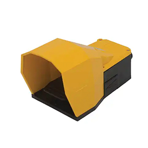
The TER 6100 configuration can be supplied with a standard protection cover or a larger protective cover designed to accommodate safety footwear.
The protective cover surrounds the pedal operating area and helps provide a defined location for the operator’s foot. In industrial environments, this can be an important consideration where the footswitch is positioned near other equipment, materials or normal operator movement.
The availability of different cover sizes also allows the machine designer to consider the type of footwear likely to be used by operators. In manufacturing, fabrication, material handling and other industrial environments, safety footwear can be substantially larger and heavier than ordinary footwear.
Standard Protection Cover
The standard protection cover provides a guarded pedal arrangement intended to help protect the operating area of the footswitch.
A protective cover can reduce exposure of the pedal to incidental contact from the side or above and provides the operator with a clearly defined area in which to place the foot.
This type of physical protection can form part of an overall machine-control strategy where deliberate pedal operation is required. The appropriate cover should be selected in conjunction with the operating mechanism and the machine’s risk assessment.
Large Protection Cover for Safety Footwear
For the 6100 version, TER also provides a large cover option intended for operators wearing safety shoes.
This is an important practical feature for industrial workplaces. Operators of production machinery are frequently required to wear protective footwear, and a pedal enclosure that is too restrictive can make the footswitch uncomfortable or difficult to operate.
A larger protective cover provides additional space around the pedal while retaining the benefits of a guarded foot control.
When selecting between the standard and large cover, consideration should be given to operator footwear, pedal accessibility, workstation layout and the frequency with which the footswitch will be used.
Single Footswitch Configurations
The TER 6100/6200 can be configured as a single footswitch for machinery requiring one primary foot-operated auxiliary command.
A single-pedal arrangement provides a straightforward interface where one machine function needs to be controlled by foot. Depending on the selected configuration, the pedal can be combined with different switching arrangements and mechanical operating features.
This configuration can be appropriate for machinery where a dedicated foot command is required without the additional space or complexity associated with multiple pedals.
Double Footswitch Configurations
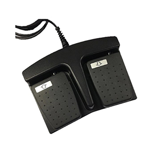
TER also provides single or double footswitch arrangements fixed to a metal plate. A double configuration allows two foot-operated controls to be positioned together as one organised operator interface.
This arrangement can be valuable where two separate machine commands need to be available to the operator by foot. Instead of installing independent footswitches in different positions, the controls can be incorporated into a common assembly.
The function assigned to each pedal is determined by the machine control design. Clear identification and appropriate spacing should be considered to minimise the possibility of the operator selecting the wrong pedal.
Metal Plate Mounting
Single and double 6100/6200 footswitches can be fixed to a metal plate, providing a stable mounting arrangement for the foot-operated controls.
Stability is an important consideration for industrial footswitches. A pedal that moves across the floor during operation can become inconvenient for the operator and may interfere with consistent machine operation.
The final installation should position the footswitch securely and appropriately in relation to the operator workstation, machinery and surrounding equipment.
Plastic Footswitch Construction
The TER 6100/6200 is available in plastic construction, providing a durable housing option for industrial machine-control applications.
The materials and components used throughout the range are designed to resist shock and wear. This is particularly important for floor-level controls because footswitches may be subjected to repeated operation, footwear contact and general activity around industrial machinery.
The suitability of the plastic configuration should be considered according to the mechanical and environmental requirements of the intended application.
Die-Cast Aluminium Construction
For applications requiring a metal construction, TER also offers the 6100/6200 in die-cast aluminium.
Die-cast aluminium provides a robust housing solution suited to demanding industrial equipment and machinery. It can be particularly attractive where a metal footswitch housing is preferred as part of the overall machine design or installation environment.
The choice between plastic and die-cast aluminium allows equipment manufacturers to select the construction that best matches the mechanical requirements, operating conditions and design objectives of the machine.
Shock and Wear Resistant Design
TER specifies the materials and components used in the 6100/6200 range as resistant to shock and wear.
This characteristic is particularly relevant for foot-operated equipment. Unlike controls protected within a machine panel, a footswitch is installed at floor level where it may be exposed to repeated footwear contact, vibration and general industrial activity.
A durable mechanical design helps the footswitch continue to provide consistent operation over its intended service life.
IP53 Ingress Protection
The TER 6100/6200 Footswitch is classified IP53, providing environmental protection appropriate to a range of industrial installations.
The first digit indicates protection against the ingress of solid foreign objects and dust at the level defined by the applicable ingress protection classification. The second digit provides protection against spraying water under the corresponding test conditions.
IP53 should be considered carefully in relation to the intended installation environment. The footswitch should not automatically be treated as suitable for environments requiring a higher degree of protection against water or other contaminants.
Machine designers should assess the actual conditions surrounding the operator workstation and select the footswitch accordingly.
Operating Temperature from -25°C to +70°C
The TER 6100/6200 is designed to operate across an ambient temperature range from -25°C to +70°C.
This broad operating range supports use in many industrial environments, including factories, workshops, production facilities and other areas where temperatures may vary considerably throughout the year or as a result of surrounding machinery and processes.
The specified storage temperature range extends from -40°C to +70°C, providing additional flexibility during transport, warehousing and periods when the machinery is not operating.
One Million Mechanical Operations
The switches used within the TER 6100/6200 range are specified for a mechanical life of one million operations.
Mechanical endurance is an important consideration when selecting a footswitch because many industrial applications involve repetitive pedal operation. A footswitch may be actuated during every production cycle, resulting in a substantial number of operations over the life of the machine.
The specified one-million-operation mechanical life provides machine builders with a defined durability reference when assessing the footswitch for the expected operating cycle of the equipment.
Safety Device to Help Prevent Accidental Operation
The TER 6100/6200 can be equipped with a safety device designed to help prevent accidental pedal operation.
In this configuration, the operator must deliberately interact with the mechanism before normal pedal movement can occur. This can reduce the likelihood of an unintended machine command caused by accidental contact with the footswitch.
This option can be particularly useful where the footswitch is positioned within the operator’s normal movement area or where deliberate pedal actuation is an important part of the machine control strategy.
The suitability of this feature should be determined through the overall machine risk assessment and control-system design.
Lock-Release Pedal Device
The TER 6100/6200 can also be fitted with a lock-release device that allows the pedal to be maintained in the pressed position.
This arrangement provides a different operating behaviour from a conventional momentary pedal. Once the required operating position has been selected, the mechanism can keep the pedal depressed according to the configuration of the footswitch.
A maintained pedal function can be useful for certain machine processes, but it is not appropriate for every application. The machine designer should determine whether maintained operation is compatible with the required control sequence and machinery safety strategy.
Choosing Between Momentary and Maintained Pedal Operation
The required pedal behaviour depends heavily on the function being controlled.
A momentary footswitch generally requires continued operator interaction for the associated control state to remain active, while a maintained or lock-release configuration can hold the pedal in its operated position.
For this reason, the mechanical pedal configuration should be selected at the same time as the electrical switching arrangement. The complete control function should be evaluated rather than choosing the pedal mechanism independently.
Emergency Stop Mushroom Pushbutton Option
The TER 6100/6200 can incorporate an emergency-stop mushroom pushbutton as part of the footswitch assembly.
TER specifies that the emergency-stop mushroom pushbutton complies with ISO 13850, providing machine manufacturers with an additional option where an emergency-stop control is required at the operator station.
Locating an emergency-stop control together with the footswitch can provide convenient access within an appropriately designed workstation. The exact location and accessibility of the emergency-stop device should be determined according to the machine design and applicable safety requirements.
Emergency Stop as Part of the Complete Safety System
An emergency-stop pushbutton forms only one component of the complete emergency-stop function.
The machine’s electrical architecture, switching components, control logic, reset behaviour and stopping performance must all be designed to achieve the required safety function.
The availability of an ISO 13850 compliant mushroom pushbutton on the TER 6100/6200 provides an appropriate operator interface component, but the safety performance of the complete machine depends on correct system design and integration.
Positive-Opening Normally Closed Contacts
The TER 6100/6200 range provides positive-opening normally closed contacts for safety functions.
Positive-opening operation creates a direct mechanical relationship between movement of the switch actuator and opening of the normally closed contact. This characteristic is particularly relevant to appropriately designed safety-related control functions.
Rather than relying solely on spring force to separate the contacts, the positive-opening mechanism provides direct mechanical action to achieve contact opening.
Where positive-opening contacts are required, the selected switch configuration and complete safety circuit should be verified against the requirements of the machine.
1NO+1NC Switching Configurations
The TER 6100/6200 can be equipped with snap-action or slow-action switches featuring 1NO+1NC contacts.
This provides one normally open and one normally closed contact within the switching arrangement. The combination allows machine-control designers to access complementary electrical states from pedal operation.
For example, the normally open contact can be used to establish a circuit when the required switching point is reached, while the normally closed contact can provide an opposite contact state.
The actual use of these contacts is determined by the electrical control architecture of the machinery.
2NO+2NC Switching Configurations
Slow-action switches with 2NO+2NC contacts are also available for the TER 6100/6200.
This configuration provides two normally open and two normally closed contacts, allowing more complex control arrangements than a basic single-pole switching configuration.
Additional contacts can be valuable where a machine control system requires multiple simultaneous switching functions or where separate circuits need to respond to the same pedal movement.
The exact contact arrangement should be selected according to the machine control schematic and required switching behaviour.
Snap-Action Switches
Snap-action switching is available with appropriate 1NO+1NC TER 6100/6200 configurations.
A snap-action mechanism changes the electrical contact state rapidly once the actuator passes its switching point. This provides a clearly defined transition between contact states and can be useful in industrial control circuits requiring distinct switching behaviour.
The suitability of snap-action switching depends on the function being controlled and the requirements of the machine electrical system.
Slow-Action Switches
TER also offers slow-action switching for the 6100/6200 range, including both 1NO+1NC and 2NO+2NC contact arrangements.
With a slow-action mechanism, movement of the electrical contacts is more directly related to movement of the mechanical actuator.
This provides different operating characteristics from a snap-action switch and allows machine designers to select the switching behaviour most appropriate to the required control function.
AC15 Industrial Control Applications
The switches used within the TER 6100/6200 are specified for AC15 utilisation category applications.
AC15 is associated with the control of electromagnetic loads within alternating-current industrial control circuits. This is consistent with the intended use of the 6100/6200 as an auxiliary machine control operating through an appropriate power interface.
The footswitch can therefore provide the operator command to the control circuit while equipment such as a contactor performs the required switching of the higher-power machine load.
M20 Cable Entry
The TER 6100/6200 uses an M20 cable gland entry for connection to the machine control wiring.
The cable gland provides the interface between the external cable and the internal switch enclosure. Correct selection and installation of the cable and gland are important for maintaining mechanical security and the intended environmental protection of the footswitch.
The cable should be appropriately supported and routed so that operator movement, machinery activity or surrounding equipment does not place unnecessary strain on the electrical termination.
Class I Insulation Category
The TER 6100/6200 is specified as insulation Class I.
This classification is an important consideration when integrating the footswitch into the electrical system of industrial machinery, particularly for configurations incorporating conductive accessible parts.
Installation should follow the applicable electrical requirements and TER’s product instructions to ensure that the footswitch is correctly incorporated into the machine.
Designed to Work Through a Power Interface
An important characteristic of the TER 6100/6200 is its intended position within the machine electrical architecture.
The footswitch provides an auxiliary control signal and acts on the machine motor through a suitable power interface such as a contactor. This separates the operator switching function from the direct switching of the machine’s primary motor load.
This architecture is common in industrial machinery because the operator control can be designed for the requirements of the control circuit while appropriately rated power components handle the higher electrical loads.
A Configurable Industrial Footswitch Platform
The TER 6100/6200 combines several configuration options within one industrial footswitch family, allowing OEMs, machine manufacturers and system integrators to select a control suited to their particular equipment.
Plastic and die-cast aluminium construction options provide flexibility in housing selection, while standard and large protective covers on the 6100 version allow the pedal area to be matched to operator and footwear requirements.
Single or double footswitch assemblies, lock-release mechanisms and safety devices for reducing accidental operation provide further mechanical flexibility.
Electrically, the availability of snap and slow-action switches, 1NO+1NC and 2NO+2NC contact configurations and positive-opening normally closed contacts provides a strong foundation for industrial auxiliary control and appropriate safety-related functions.
Combined with IP53 protection, a -25°C to +70°C operating temperature range and a mechanical life of one million switch operations, the TER 6100/6200 provides a robust and adaptable foot-operated control solution for industrial machinery.
Electrical Specifications of the TER 6100/6200 Footswitch
The TER 6100/6200 Footswitch range provides a selection of electrical switching configurations designed for low-voltage auxiliary control circuits used within industrial machinery. Rather than directly switching the main motor load, the footswitch is intended to operate through an appropriate power interface, such as a contactor, allowing the pedal to function as an operator control within the wider machine electrical system.
Different switch configurations are available within the 6100/6200 family, allowing machine builders and electrical designers to select the contact arrangement and switching characteristics appropriate to the application. Available options include snap-action and slow-action switches, 1NO+1NC and 2NO+2NC contact arrangements, and positive-opening normally closed contacts for applicable safety-related functions.
The electrical ratings vary according to the selected switch configuration. For this reason, the complete TER 6100/6200 should be specified according to the requirements of the actual control circuit rather than assuming that one electrical rating applies universally to every version.
AC15 Utilisation Category
The TER 6100/6200 is designed for AC15 utilisation category applications. AC15 is an industrial utilisation category associated with the control of electromagnetic loads in alternating-current control circuits.
This type of classification is particularly relevant to machinery incorporating contactors, relays and other electromagnetic control devices. The footswitch provides the operator command, while the connected control system processes that command and operates the appropriate machine power components.
Using an utilisation category provides machine designers with more meaningful information than considering voltage alone because the switching capability of electrical contacts depends on the characteristics of the connected load.
Rated Operational Current
Depending on the selected switch configuration, TER specifies AC15 rated operational currents including 3 A at 250 Vac and 1.9 A at 380 Vac.
These ratings define the operational switching capability of the applicable contacts under the specified AC15 conditions.
The correct rating should be compared with the voltage, current and load characteristics of the machine control circuit before the footswitch is selected.
Where the connected control load exceeds the rating of the selected switch, an appropriate intermediate control device should be incorporated into the electrical architecture.
3 A at 250 Vac AC15 Rating
Applicable TER 6100/6200 switch configurations provide a rated operational current of 3 A at 250 Vac under AC15 utilisation conditions.
This rating can support a broad range of conventional industrial auxiliary control applications where the footswitch operates electromagnetic equipment through the machine control circuit.
The actual connected load should always be verified because the nominal system voltage alone does not determine whether a switching device is suitable.
1.9 A at 380 Vac AC15 Rating
Other applicable configurations provide a rated operational current of 1.9 A at 380 Vac under AC15 utilisation conditions.
The lower current rating at the higher operating voltage illustrates the importance of considering the complete published switching specification when selecting the footswitch.
Machine designers should confirm that the selected switch type is suitable for the actual control voltage and load rather than applying the rating of another 6100/6200 configuration.
Conventional Free-Air Thermal Current
The switches used within the TER 6100/6200 range have a conventional free-air thermal current rating of 10 A.
The thermal-current rating represents the current the device can carry under specified conditions without exceeding defined temperature limits. It should not be confused with the operational switching current associated with the AC15 utilisation category.
A device may have a relatively high thermal-current rating while having a lower permissible operational current when repeatedly switching an electromagnetic load.
Both values should therefore be considered when evaluating the electrical requirements of an industrial control circuit.
Rated Insulation Voltage
Rated insulation voltage varies according to the switch configuration selected for the TER 6100/6200 Footswitch.
TER specifies rated insulation voltage values of up to 300 Vac or 500 Vac depending on the applicable switch type.
Rated insulation voltage is an important characteristic of the electrical insulation system and should be considered alongside operational voltage, utilisation category and installation conditions.
When selecting the footswitch, the insulation rating of the actual switch configuration should be confirmed against the requirements of the machine electrical system.
300 Vac Insulation Configurations
Applicable TER switch configurations within the 6100/6200 range provide a rated insulation voltage of 300 Vac.
These versions may be appropriate for machinery operating with lower-voltage auxiliary control systems, provided that all other electrical ratings and environmental requirements are satisfied.
The insulation voltage should not be interpreted as the operational switching rating. It is a separate specification relating to the insulation characteristics of the device.
500 Vac Insulation Configurations
Other switch configurations provide a rated insulation voltage of up to 500 Vac.
This higher insulation rating gives machine designers another option when configuring the 6100/6200 for industrial electrical systems.
As with all electrical specifications, the rating applicable to the exact switch installed within the footswitch should be confirmed during product selection.
Snap-Action 1NO+1NC Switching
The TER 6100/6200 can be equipped with snap-action switching incorporating 1NO+1NC contacts.
A 1NO+1NC configuration provides one normally open and one normally closed electrical contact. During pedal operation, the contact states change according to the mechanical switching point of the device.
The snap-action mechanism produces a rapid transition once the defined operating point is reached, providing a distinct electrical change of state.
This configuration can be useful for conventional industrial machine-control applications where clearly defined switching behaviour is required.
Slow-Action 1NO+1NC Switching
Slow-action switching with 1NO+1NC contacts is also available within the TER 6100/6200 range.
Unlike a snap-action mechanism, slow-action contact movement is more directly related to the movement of the mechanical actuator.
This different switching characteristic allows machine designers to select the type of electrical behaviour that best matches the required control function.
The suitability of slow or snap-action switching should be considered together with the pedal mechanism, required machine response and safety architecture.
Slow-Action 2NO+2NC Switching
For applications requiring additional electrical contacts, TER provides slow-action switch configurations with 2NO+2NC contacts.
This arrangement provides two normally open and two normally closed contacts associated with pedal operation.
Additional contacts can be useful where several control signals need to respond to the same mechanical pedal movement or where the machine architecture requires separate electrical circuits to be switched simultaneously.
The availability of 2NO+2NC switching increases the flexibility of the 6100/6200 for more complex industrial control systems.
Normally Open Contacts
A normally open contact remains electrically open when the switch is in its normal unactuated state. Pedal operation causes the contact to close when the appropriate switching point is reached.
Within a machine control circuit, this contact can be used to provide an electrical command following deliberate operator actuation of the footswitch.
The exact machine function associated with the normally open contact depends entirely on the control-system design.
Normally Closed Contacts
A normally closed contact provides electrical continuity in its normal state and opens when the switching mechanism reaches its defined operating condition.
Normally closed contacts are widely used throughout industrial control systems and can provide complementary control logic to normally open contacts.
Applicable TER 6100/6200 configurations also provide positive-opening operation of the normally closed contacts for safety functions.
Positive-Opening Contact Operation
Positive-opening operation is an important feature of applicable TER 6100/6200 configurations. It establishes a direct mechanical relationship between actuator movement and opening of the normally closed electrical contact.
This means that opening of the specified NC contact is achieved through direct mechanical action rather than relying solely on spring force.
Positive-opening contacts can be important components within appropriately engineered safety-related machine control functions.
The presence of a positive-opening contact does not independently determine the safety level of the complete system. The control architecture, redundancy, diagnostics, stopping behaviour and other system characteristics must be considered as part of the complete machinery risk assessment and safety design.
Electrical Switching and the Machine Contactor
The TER 6100/6200 is intended to operate within an auxiliary control circuit and act on the machine motor through an appropriate power interface such as a contactor.
This arrangement separates the operator interface from the primary machine power circuit. The footswitch handles the appropriate control signal while the contactor or other suitable power-switching device manages the higher electrical load associated with the machine motor.
This architecture can also make it easier for machine designers to incorporate additional control logic, interlocks and safety functions between the footswitch command and final machine operation.
Footswitch as an Operator Input Device
Within the complete machine architecture, the 6100/6200 should be considered an operator input device rather than a complete control system.
Pedal movement creates the required electrical contact state, but the resulting machine response is determined by the equipment connected to those contacts.
This distinction allows the TER footswitch to be incorporated into a wide variety of machine designs because the same fundamental pedal command can be processed differently according to the application.
Emergency-Stop Pushbutton Integration
The TER 6100/6200 can be configured with an emergency-stop mushroom pushbutton, providing an additional operator control within the footswitch assembly.
TER specifies an emergency-stop mushroom pushbutton compliant with ISO 13850. This can provide machine manufacturers with a practical option where emergency-stop access is required close to the foot-operated workstation.
The emergency-stop device should be positioned so that it can be reached readily when required and should be integrated into an appropriately designed emergency-stop function.
Emergency Stop and Machine Safety
An emergency-stop mushroom pushbutton is only the operator interface portion of the complete emergency-stop function.
The electrical safety circuit, machine control system, power switching components and stopping behaviour must all be designed to provide the required response when the emergency-stop control is operated.
Resetting an emergency-stop device should not automatically cause hazardous machine movement. The complete machine control strategy should determine how operation can safely resume following an emergency stop.
Safety Device Against Accidental Pedal Operation
TER offers a pedal safety device intended to help prevent accidental operation of the 6100/6200 Footswitch.
This mechanism requires deliberate operator interaction before normal pedal actuation can occur, reducing the likelihood of an unintended command caused by incidental contact with the pedal.
Such a feature can be particularly valuable in work areas where the operator frequently moves their feet around the footswitch or where other objects could potentially contact the pedal.
Safety Device Selection
The requirement for a pedal safety device should be determined as part of the machine risk assessment.
Factors can include the nature of the controlled movement, the consequences of unintended operation, the position of the footswitch, operator posture, surrounding equipment and the frequency of pedal use.
A protective cover and pedal safety mechanism can help reduce the potential for unintended actuation, but these mechanical features should be considered as part of the complete machine safety strategy.
Lock-Release Mechanism
A lock-release device is available to maintain the pedal in its pressed position where this operating behaviour is required.
This configuration allows the pedal to remain mechanically actuated without continuous operator pressure.
Maintained pedal operation can be useful for selected machine functions, but it should only be used where a latched command is appropriate to the process and compatible with the safety requirements of the machine.
Mechanical Life of One Million Operations
TER specifies a mechanical life of one million operations for the switches used within the 6100/6200 Footswitch range.
This rating provides an important reference when evaluating the product for repetitive industrial machine-control applications.
The actual service life achieved in an installation can be influenced by factors including operating frequency, electrical loading, environmental conditions, mechanical configuration and maintenance.
For machines with particularly high cycle rates, expected annual pedal operations should be considered during product selection and preventive maintenance planning.
IP53 Environmental Protection
The TER 6100/6200 provides IP53 ingress protection.
This protection rating supports use in a range of industrial environments while also establishing clear limits that should be considered during machine design.
The footswitch should be positioned away from environmental conditions that exceed its specified ingress protection capability.
Where an application involves substantial water exposure, washdown processes or other demanding contamination conditions, the required enclosure protection should be evaluated before selecting the 6100/6200.
Importance of Correct Cable Gland Installation
The TER 6100/6200 uses an M20 cable gland entry for machine wiring.
Correct cable-gland installation is important because the cable entry forms part of the interface between the internal electrical components and the surrounding environment.
The gland should be appropriate for the cable being used and should be installed so that the cable is securely retained without damage to the outer sheath.
Incorrect cable selection or gland installation can compromise mechanical strain relief and may affect the intended environmental protection of the footswitch assembly.
Screw-Type Electrical Terminals
The internal switches use screw-type terminal arrangements for connection to the machine control wiring.
Screw terminals provide a conventional and serviceable termination method for industrial equipment, allowing appropriately prepared conductors to be securely connected to the switch contacts.
Electrical installation should be completed with the machine isolated from its energy source and by personnel competent to perform the required work.
Conductor Preparation and Termination
Conductors should be prepared and terminated according to the requirements of the selected switch and machine wiring system.
Connections should be mechanically secure and arranged so that movement of the external cable does not place unnecessary stress on the internal switch terminals.
After installation, wiring should be checked to confirm that no loose conductors, exposed strands or incorrectly routed cables can interfere with the mechanical operation of the pedal or switching mechanism.
Class I Electrical Construction
The TER 6100/6200 is specified as insulation Class I.
Class I equipment relies on basic insulation together with protective earthing of applicable accessible conductive parts as part of protection against electric shock.
This classification is particularly relevant to configurations incorporating die-cast aluminium construction.
Protective earthing and electrical installation should be completed according to the manufacturer’s requirements and the applicable electrical standards for the machine.
Die-Cast Aluminium for Heavy Industrial Applications
The availability of die-cast aluminium construction gives machine designers a robust housing option for demanding industrial applications.
Metal construction can be attractive where the footswitch may experience regular mechanical contact or where the surrounding machine equipment is predominantly constructed from metal.
The housing material should nevertheless be selected according to the complete application rather than assuming that one material is universally preferable.
Plastic Construction for Industrial Machinery
Plastic construction is also available within the TER 6100/6200 range and provides an alternative for applications where its mechanical and environmental characteristics are appropriate.
The materials and components are designed to resist shock and wear, supporting the repeated mechanical interaction expected from a floor-mounted operator control.
The availability of both plastic and die-cast aluminium versions increases the range of machines into which the 6100/6200 can be integrated.
Standard and Large Protective Covers
The 6100 version can be supplied with standard or large protective covers, allowing the pedal area to be matched more closely to operator requirements.
The large cover is particularly useful where operators wear industrial safety footwear, providing additional space for the shoe or boot within the protected operating area.
Protective covers can also help reduce direct accidental contact with the pedal from surrounding objects or normal operator movement.
Footswitch Positioning and Operator Ergonomics
The physical position of the footswitch can have a significant effect on operator comfort and control.
The pedal should be positioned so that the operator can reach it naturally without excessive stretching, twisting or maintaining an unstable working posture.
For repetitive production tasks, even relatively small ergonomic problems can become significant when the pedal is operated hundreds of times during a working shift.
Machine designers should therefore consider pedal location, operator stance, safety footwear and the surrounding work area when installing the 6100/6200.
Stable Footswitch Mounting
TER provides single and double footswitch arrangements fixed to a metal plate, allowing a stable operator control assembly to be created.
Secure mounting helps prevent the footswitch from moving away from its intended position during repeated operation.
This can improve operator consistency and reduce the need to reposition the pedal during normal machine use.
Double Footswitch Electrical Integration
A double footswitch configuration allows two separate pedal commands to be incorporated into one operator station.
Each pedal can be connected according to the machine control architecture, allowing two different auxiliary functions to be controlled by foot.
Where multiple pedals are used, the machine design should make the purpose of each pedal clear to the operator. Physical arrangement, labelling and operating logic can all help reduce the potential for selection errors.
Control Circuit Design Considerations
Correct integration of the TER 6100/6200 requires consideration of the complete machine control circuit.
The designer should confirm the operational voltage, current, utilisation category, contact arrangement and required switching behaviour before selecting the final configuration.
Where positive-opening contacts or emergency-stop controls form part of a safety-related function, the safety architecture and required performance should also be established before component selection.
Selecting 1NO+1NC or 2NO+2NC Contacts
A 1NO+1NC configuration can provide a practical solution where one normally open and one normally closed signal are sufficient for the required control logic.
Where additional simultaneous contact states are required, a 2NO+2NC slow-action configuration can provide greater electrical flexibility.
The decision should be based on the actual machine schematic rather than selecting the greater number of contacts by default.
A correctly specified switch can simplify wiring and control logic while ensuring that the required signals are available when the pedal is operated.
Selecting Snap-Action or Slow-Action Switching
The choice between snap-action and slow-action switching depends on the desired relationship between mechanical pedal movement and electrical contact operation.
Snap-action switching provides a rapid change of state once the switching threshold has been reached. Slow-action switching follows actuator movement more directly and is available with additional contact configurations.
Machine designers should evaluate the switching characteristics in conjunction with the pedal mechanism and intended machine function.
Electrical and Mechanical Configuration Working Together
One of the strengths of the TER 6100/6200 range is the ability to combine mechanical pedal options with different electrical switching arrangements.
A machine manufacturer can select the required housing material, protective cover, single or double arrangement, accidental-operation safety mechanism and lock-release behaviour before matching these characteristics with the appropriate electrical contacts.
This modular approach allows the footswitch to be configured around the actual needs of the machinery rather than forcing the control system to adapt to one fixed pedal design.
Technical Flexibility for OEM Machine Builders
For OEMs and industrial equipment manufacturers, configurable operator controls can simplify the development of different machine variants.
The TER 6100/6200 provides several mechanical and electrical options within a common product family, making it possible to specify different footswitch configurations for different equipment models while retaining a consistent overall operator-control concept.
Applications can be matched according to control voltage, contact requirements, housing construction, operator footwear, required safety mechanisms and installation arrangement.
Reliable Electrical Control for Industrial Equipment
The TER 6100/6200 combines robust foot-operated mechanical control with electrical switching options designed specifically for industrial auxiliary circuits.
AC15 ratings, 10 A conventional free-air thermal current, rated insulation voltages up to 500 Vac and configurable snap or slow-action contacts provide machine designers with the technical characteristics required for a broad range of machine-control applications.
Positive-opening normally closed contacts provide an important option for appropriately designed safety-related functions, while 1NO+1NC and 2NO+2NC arrangements allow the switching architecture to be matched to the requirements of the machine.
Combined with M20 cable entry, Class I construction, IP53 environmental protection and a mechanical switch life of one million operations, the TER 6100/6200 provides a versatile electrical and mechanical interface for industrial foot-operated machine control.
Industrial Applications for the TER 6100/6200 Footswitch
The TER 6100/6200 Footswitch is designed for auxiliary control of industrial machinery where reliable foot-operated operator input is required. Its robust construction, configurable pedal arrangements and industrial switch options make it suitable for a wide range of machine environments where the operator may need to keep both hands free while activating or controlling a machine function.
TER identifies the 6100/6200 for applications including crane control cabins, automation and assembly lines, machine tools, plastic injection machinery, printing equipment, strapping machines and medical equipment. These applications demonstrate the versatility of the product across both heavy industrial machinery and more specialised equipment.
The 6100/6200 is intended to operate within a low-voltage machine control circuit. The footswitch provides the operator input, while the machine motor or higher-power load is controlled through an appropriate power interface such as a contactor.
Automation and Assembly Line Applications
Automation and assembly systems frequently require operators to perform manual handling tasks while also interacting with machine controls. A footswitch provides a practical method of moving selected control functions away from the hands and onto the feet.
This can be especially useful where operators are positioning components, holding workpieces, supporting materials or carrying out repetitive assembly tasks. The footswitch can provide the required electrical command while leaving both hands available for the production process.
Single or double 6100/6200 configurations allow the operator station to be tailored according to the number of required foot-operated functions.
Machine Tool Applications
Machine tools are another major application area for industrial foot controls. Operators may need to position material or manipulate a workpiece while initiating an auxiliary machine function.
The TER 6100/6200 can provide this operator input through an appropriately designed machine control circuit. Different pedal mechanisms and switch configurations can be selected according to the required operating behaviour.
The standard or large protective cover available on the 6100 version can also be useful in workshop environments where operators wear safety footwear and where accidental pedal contact needs to be considered.
Plastic Injection Machine Applications
TER specifically identifies plastic injection machines as an application for the 6100/6200 Footswitch.
Injection moulding machinery can combine automated cycles with manual loading, setup, part removal and operator-controlled processes. A foot-operated auxiliary control can provide an additional input method where keeping the hands available improves the working arrangement.
The selected footswitch configuration should be matched to the electrical and mechanical requirements of the machine and to the operating environment surrounding the workstation.
Printing Machine Applications
The TER 6100/6200 can also be applied to industrial printing machinery. Operators working with printing equipment may need to guide material, position stock or make adjustments while controlling an auxiliary machine function.
A footswitch allows a suitable command to be initiated without requiring the operator to release the material or reach for a panel-mounted control.
Where more than one foot-operated function is required, a double footswitch arrangement mounted on a metal plate can provide a more organised operator interface.
Strapping Machine Applications
Strapping machines are another application specifically identified by TER for the 6100/6200 Footswitch.
Operators may need to hold cartons, bundles or products in position while initiating a strapping cycle or another machine function. Foot operation can allow the hands to remain engaged with the load while the required auxiliary command is generated.
This can improve the practicality of the operator workstation where foot control is compatible with the machine design and risk assessment.
Crane Control Cabin Applications
TER includes the 6100/6200 among its products for crane control cabins. Crane operator stations can contain multiple joysticks, selectors and hand-operated controls, creating demand for additional functions that can be assigned to foot operation.
A footswitch can provide an additional operator input without occupying valuable space on a joystick or control console.
The exact function assigned to the 6100/6200 should be determined according to the crane control system, operational requirements and applicable safety standards.
Medical Equipment Applications
TER also identifies medical equipment as a potential application area for the 6100/6200 range.
Foot-operated controls can be useful in specialised equipment where the operator needs to keep both hands available while controlling an auxiliary electrical function.
The suitability of any particular 6100/6200 configuration for medical equipment should be assessed according to the complete equipment design, electrical system, operating environment and applicable regulatory requirements.
Hands-Free Operator Control
One of the primary advantages of a footswitch is the ability to transfer an appropriate control function away from the operator’s hands.
In many industrial processes, the hands are already required for positioning, supporting or manipulating materials. A foot-operated input can reduce the need to interrupt these tasks simply to activate a separate pushbutton or selector.
The final workstation design should ensure that the operator can reach and operate the footswitch naturally without compromising posture, balance or safe interaction with the machine.
Single Footswitch Applications
A single TER 6100/6200 Footswitch is suitable where one dedicated foot-operated function is required.
This configuration can provide a simple operator interface while still allowing selection of different switch arrangements, protective covers and mechanical pedal mechanisms.
The single version can be particularly appropriate where the machine uses one repeated auxiliary command and additional foot controls are unnecessary.
Double Footswitch Applications
A double footswitch assembly provides two separate pedal positions mounted together on a metal plate.
This arrangement can support machinery requiring two independent foot-operated commands while keeping the controls organised within a common operator station.
The function of each pedal should be clearly identified and the machine control logic should be designed to minimise the likelihood of operating the wrong function.
Standard and Large Cover Selection
The 6100 version can be supplied with either a standard protection cover or a larger cover designed for safety footwear.
The larger cover can provide improved access where operators are wearing industrial work boots or other protective footwear.
Choosing the correct cover should take into account operator comfort, pedal accessibility, accidental operation risk and the physical layout of the workstation.
Reducing Accidental Pedal Operation
The TER 6100/6200 can be fitted with a safety device designed to reduce accidental pedal activation.
TER’s maintenance instructions specify that this device should be checked periodically. One recommended check is to press the pedal from the edge; when the safety device is operating correctly, the pedal should not actuate from this unintended direction.
This provides machine operators and maintenance personnel with a practical method of confirming that the anti-accidental-operation mechanism remains functional.
Maintained Pedal Operation
The 6100/6200 can also be equipped with a lock-release mechanism that keeps the pedal in the pressed position.
This configuration can be useful where the controlled process requires a maintained command rather than momentary foot pressure.
Because maintained operation changes the behaviour of the control significantly, it should only be selected where it is appropriate to the machine function and compatible with the overall safety strategy.
Emergency Stop Integration
An emergency-stop mushroom pushbutton can be incorporated into the TER 6100/6200 Footswitch assembly.
TER specifies that this mushroom pushbutton complies with ISO 13850, providing machine designers with an additional emergency-control option at the operator station.
The complete emergency-stop function must still be designed around the machine’s safety requirements, including electrical architecture, stopping behaviour, reset logic and the accessibility of the emergency-stop device.
Positive-Opening Contacts for Safety Functions
Applicable 6100/6200 configurations provide positive-opening normally closed contacts for safety functions.
Positive-opening operation provides direct mechanical separation of the NC contact when the switching mechanism is actuated. This characteristic can be important where the switch forms part of an appropriately designed safety-related control function.
The overall safety performance of the machine depends on the complete system rather than on the footswitch alone. Safety relays, control logic, power switching elements and machine stopping behaviour may all form part of the required architecture.
Correct Electrical Integration
The TER 6100/6200 is an electromechanical control device for low-voltage machine control circuits.
TER’s operating instructions reference its use with electrical equipment for machinery and identify the relevant low-voltage control context. The footswitch should therefore be incorporated into a correctly designed machine control circuit rather than treated as a general-purpose high-power switching device.
The selected contact arrangement, operational voltage and current rating should be verified against the requirements of the actual application.
Machine Control Through a Contactor
TER describes the 6100/6200 as acting on the machine motor through a power interface such as a contactor.
This means that the footswitch generates the operator command while a separate appropriately rated device handles the machine’s power load.
This approach allows the footswitch to operate within the auxiliary circuit and helps machine designers integrate additional interlocking, safety and control logic between operator input and final machine operation.
Installation Environment
The 6100/6200 is designed for industrial environments and can operate across a temperature range from -25°C to +70°C.
TER’s current operating instructions also state that the 6100 is suitable for use in tropical environments and severe climatic conditions within its specified operating range.
However, the instructions identify important environmental limitations that must be considered before installation.
Not Intended for Potentially Explosive Atmospheres
TER specifies that the standard 6100 Footswitch is not suitable for use in potentially explosive atmospheres.
Where a machine is installed in an environment containing potentially explosive gases, vapours or dust, equipment specifically certified for that hazardous environment should be selected.
The standard 6100/6200 configuration should not be assumed to provide hazardous-area protection.
Avoid Corrosive Environments
The manufacturer’s operating instructions also state that the standard 6100 Footswitch is not intended for environments containing corrosive agents or high concentrations of sodium chloride such as saline mist.
This limitation is particularly important for installations in highly corrosive industrial processes or locations exposed to substantial salt contamination.
The environmental conditions should therefore be reviewed alongside the IP53 rating before the product is selected.
IP53 Environmental Protection
The TER 6100/6200 is rated IP53.
This provides defined protection against solid contaminants and spraying water under the conditions associated with the IP classification.
The rating should not be interpreted as suitable for unrestricted washdown or immersion. Applications involving substantial water exposure, pressure cleaning or more severe contamination should be assessed against the actual ingress-protection requirement.
Footswitch Positioning
The footswitch should be installed in a position that allows deliberate and comfortable operator access.
The operator should not need to overreach, twist excessively or adopt an unstable posture to operate the pedal.
The location should also minimise the possibility of accidental contact by personnel, workpieces, trolleys or other equipment moving through the work area.
Keeping the Pedal Area Clear
TER specifically recommends removing chips, stones, rags and other objects that could obstruct pedal operation.
This is particularly important in machine shops, fabrication areas and production environments where swarf, offcuts and debris can accumulate near floor-level equipment.
The pedal should remain clear throughout operation so that it can move and return correctly without mechanical interference.
Periodic Inspection of the Safety Device
Where an anti-accidental-operation safety mechanism is fitted, TER recommends periodically checking that it is intact and functioning correctly.
The manufacturer’s instructions describe testing the mechanism by attempting to press the pedal from the edge. The pedal should not operate when the safety device is functioning correctly.
This simple inspection can be incorporated into routine machine maintenance procedures.
Checking Cover Fasteners
TER recommends periodically checking and tightening the screws used to close the footswitch cover.
Secure cover fasteners help maintain the mechanical integrity of the enclosure and protect the internal components.
Loose fasteners should be addressed promptly as part of preventive maintenance.
Inspecting the Cable Clamp
The manufacturer’s maintenance instructions also recommend checking that the wire clamp is securely fastened.
The cable sheath should provide complete protection at the entry point so that internal conductors are not exposed to unnecessary movement or mechanical stress.
Because the footswitch is located at floor level, secure cable retention is especially important where the wiring could otherwise be disturbed by operator movement or surrounding equipment.
Checking the Protective Cover
The footswitch cover should be inspected periodically for damage.
Cracking, impact damage, deformation or other deterioration could affect the protection of the pedal or internal components.
A damaged enclosure should be assessed before the machine is returned to normal service.
Cleaning the TER 6100/6200 Footswitch
TER recommends simple cleaning methods for routine maintenance.
The manufacturer’s instructions specify the use of compressed air at approximately 1 atmosphere and a damp cloth to remove contamination.
Cleaning should be carried out in a manner that does not damage the housing, pedal mechanism, cable entry or internal electrical components.
Avoiding Oils, Acids and Solvents
TER’s operating instructions warn against contact with substances including oil, acids and solvents that may damage the footswitch.
This should be considered when the footswitch is installed near machining processes, chemical systems or other equipment where aggressive fluids may be present.
Where exposure cannot be avoided, the suitability of the product for the environment should be reviewed before installation.
Maintenance for Long-Term Reliability
The TER 6100/6200 does not require complex routine maintenance, but regular basic inspection can help preserve reliable operation.
Cover fasteners, cable retention, pedal clearance and any fitted safety mechanism should be checked periodically. Contamination around the pedal should be removed and damage should be investigated promptly.
Preventive maintenance intervals can be established according to operating frequency, environmental conditions and the maintenance strategy of the machine.
One Million Operation Mechanical Life
The switches used within the TER 6100/6200 range are rated for a mechanical life of one million operations.
This endurance makes the product suitable for many repetitive industrial control applications, although operating frequency should be considered when planning service intervals.
For very high-cycle production machinery, machine builders can estimate annual pedal operations and incorporate the footswitch into the preventive maintenance schedule accordingly.
Selecting the Correct Switch Arrangement
The 6100/6200 can use snap or slow-action switches with 1NO+1NC contacts or slow-action switches with 2NO+2NC contacts.
The correct configuration depends on the electrical control logic required by the machine.
A simple command may only require one normally open and one normally closed contact, while more complex applications may benefit from additional contact sets.
Selecting the Correct Mechanical Configuration
Electrical requirements should be considered together with the physical pedal arrangement.
Machine designers can select standard or large protective covers on appropriate 6100 versions, single or double assemblies, anti-accidental-operation mechanisms and lock-release arrangements.
The best configuration is therefore determined by operator interaction, footwear, installation space, control requirements and machine safety considerations.
Plastic or Die-Cast Aluminium Construction
The TER 6100/6200 is available in plastic or die-cast aluminium construction.
This provides additional flexibility when matching the footswitch to the mechanical requirements and design preferences of the machine.
Both configurations are intended for industrial applications, with TER describing the materials and components as resistant to shock and wear.
CE Marking
TER identifies CE marking among the certifications for the 6100/6200 Footswitch range.
Product certification and marking should always be considered together with the requirements of the complete machine and the market in which the equipment will be supplied.
The use of a CE-marked component does not by itself establish compliance of the finished machine.
Advantages for OEM Machine Builders
The configurable nature of the TER 6100/6200 makes it particularly useful for OEM machine manufacturers.
A manufacturer can select from different housing materials, cover sizes, single or double pedal assemblies, switch arrangements and operating mechanisms while retaining a consistent footswitch family across multiple equipment models.
This can simplify product standardisation, spare-parts planning and operator-interface design across a machine range.
Advantages for Automation System Integrators
Automation specialists and system integrators can also benefit from the variety of electrical options available within the 6100/6200 family.
AC15 switch ratings, positive-opening contacts and multiple NO/NC arrangements allow the footswitch to be integrated into a range of industrial control architectures.
The ability to operate through contactors and other power interfaces means the pedal can be incorporated into systems ranging from relatively simple relay logic through to more sophisticated machine control architectures.
Choosing a TER 6100/6200 Footswitch
The correct TER 6100/6200 Footswitch should be selected by considering the complete application rather than focusing on one specification.
Important factors include the number of required pedals, protective cover size, operator footwear, switch type, NO and NC contact requirements, maintained or momentary pedal behaviour, accidental-operation protection, environmental exposure, electrical ratings and any requirement for emergency-stop integration.
Reviewing these factors together helps ensure that the selected configuration provides the required mechanical and electrical behaviour for the machinery.
TER 6100/6200 Footswitch from Control Devices
Control Devices supplies specialised industrial control, sensing and operator-interface products for machinery, automation and equipment applications. The TER 6100/6200 Footswitch provides another flexible industrial control solution for customers requiring dependable foot-operated auxiliary machine control.
With plastic or die-cast aluminium construction, single or double pedal arrangements, standard or large protective covers and multiple switch configurations, the 6100/6200 can be tailored to suit a wide variety of equipment requirements.
Control Devices can assist customers with product selection and technical information to help identify the most suitable TER 6100/6200 configuration for the electrical, mechanical and environmental requirements of the application.
Why Choose the TER 6100/6200 Industrial Footswitch?
The TER 6100/6200 combines robust construction, configurable electrical switching and practical operator-control options within one industrial footswitch family.
Its IP53 enclosure, -25°C to +70°C operating temperature range and shock and wear resistant materials support use in demanding machinery environments.
Positive-opening NC contacts, snap and slow-action switch options and 1NO+1NC or 2NO+2NC arrangements provide flexibility when developing industrial auxiliary and appropriately engineered safety-related control functions.
Standard and large protective covers, single and double assemblies, anti-accidental-operation safety devices and lock-release mechanisms allow the physical operator interface to be configured according to the machine and workstation.
Reliable Foot-Operated Control for Industrial Machinery
The TER 6100/6200 Footswitch provides OEMs, machine builders and system integrators with a versatile method of incorporating foot-operated commands into industrial equipment.
Its intended use within low-voltage auxiliary circuits and operation through a suitable power interface such as a contactor make it well suited to conventional industrial machine-control architectures.
From automation and assembly systems to machine tools, plastic injection machines, printing equipment, strapping machines, crane control cabins and specialised equipment, the 6100/6200 provides a rugged and adaptable operator interface.
With configurable switching, durable materials, protective cover options and multiple pedal operating arrangements, the TER 6100/6200 offers a practical solution for industrial applications requiring dependable foot-operated auxiliary control.